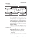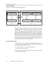
USART Operation: SPI Mode
14-8
USART Peripheral Interface, SPI Mode
Receive Enable
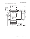
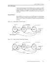
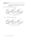
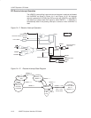
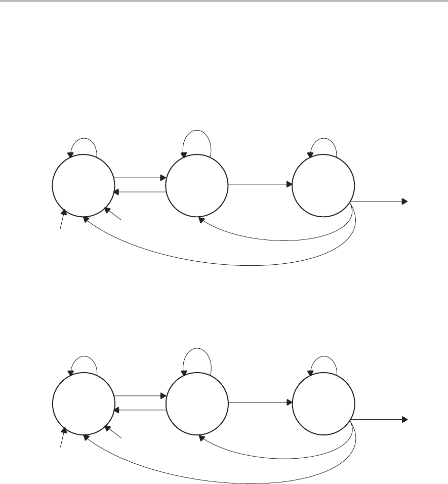
The SPI receive enable state diagrams are shown in Figure 14−6 and
Figure 14−7. When USPIEx = 0, UCLK is disabled from shifting data into the
RX shift register.
Figure 14−6. SPI Master Receive-Enable State Diagram
Idle State
(Receiver
Enabled)
Receive
Disable
Receiver
Collects
Character
USPIEx = 0
No Data Written
to UxTXBUF
Not Completed
USPIEx = 1
USPIEx = 0
USPIEx = 1
Handle Interrupt
Conditions
Character
Received
USPIEx = 1
USPIEx = 0
SWRST
PUC
Data Written
to UxTXBUF
Figure 14−7. SPI Slave Receive-Enable State Diagram
Idle State
(Receive
Enabled)
Receive
Disable
Receiver
Collects
Character
USPIEx = 0
No Clock at UCLK
Not Completed
USPIEx = 1
USPIEx = 0
USPIEx = 1
Handle Interrupt
Conditions
Character
Received
USPIEx = 1
USPIEx = 0
SWRST
PUC
External Clock
Present


