I
2
C Module Operation
15-4
USART Peripheral Interface, I
2
C Mode
15.2 I
2
C Module Operation
The I
2
C module supports any slave or master I
2
C-compatible device.
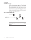
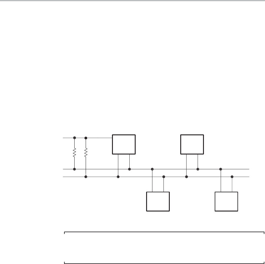
Figure 15−2 shows an example of an I
2
C bus. Each I
2
C device is recognized
by a unique address and can operate as either a transmitter or a receiver. A
device connected to the I
2
C bus can be considered as the master or the slave
when performing data transfers. A master initiates a data transfer and gener-
ates the clock signal SCL. Any device addressed by a master is considered
a slave.
I
2
C data is communicated using the serial data pin (SDA) and the serial clock
pin (SCL). Both SDA and SCL are bidirectional, and must be connected to a
positive supply voltage using a pull-up resistor.
Figure 15−2. I
2
C Bus Connection Diagram
MSP430
V
CC
Serial Data (SDA)
Serial Clock (SCL)
Device A
Device B
Device C
Note: SDA and SCL Levels
The MSP430 SDA and SCL pins must not be pulled up above the MSP430
V
CC
level.


