


Timer_B Operation
12-10
Timer_B
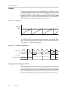
Changing the Value of Period Register TBCL0
When changing TBCL0 while the timer is running, and counting in the down
direction, and when the TBCL0 load mode is immediate, the timer continues
its descent until it reaches zero. The new period takes effect after the counter
counts down to zero.
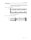
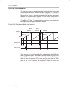
If the timer is counting in the up direction when the new period is latched into
TBCL0, and the new period is greater than or equal to the old period, or greater
than the current count value, the timer counts up to the new period before
counting down. When the timer is counting in the up direction, and the new
period is less than the current count value when TBCL0 is loaded, the timer
begins counting down. However, one additional count may occur before the
counter begins counting down.
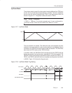
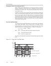
Use of the Up/Down Mode
The up/down mode supports applications that require dead times between
output signals (see section Timer_B Output Unit). For example, to avoid
overload conditions, two outputs driving an H-bridge must never be in a high
state simultaneously. In the example shown in Figure 12−9 the t
dead
is:
t
dead
= t
timer
× (TBCL1 − TBCL3)
With: t
dead
Time during which both outputs need to be inactive
t
timer
Cycle time of the timer clock
TBCLx Content of compare latch x
The ability to simultaneously load grouped compare latches assures the dead
times.
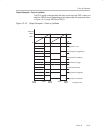
Figure 12−9. Output Unit in Up/Down Mode
TBIFG
0h
TBR
(max)
Output Mode 2: Toggle/Reset
Output Mode 6: Toggle/Set
TBCL0
TBCL1
EQU1
TBIFG
Interrupt Events
EQU1
EQU0
EQU1 EQU1
EQU0
TBCL3
EQU3 EQU3EQU3 EQU3
Dead Time