I
2
C Module Operation
15-12
USART Peripheral Interface, I
2
C Mode
Automatic Data Byte Counting
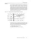
Automatic data byte counting is supported in master mode with the I2CNDAT
register. When I2CRM = 0, the number of bytes to be received or transmitted
is written to I2CNDAT. A STOP condition is automatically generated after
I2CNDAT number of bytes have been transferred.
Note: I2CNDAT Register
Do not change the I2CNDAT register while I2CBB = 1 and I2CRM = 0.
Otherwise, unpredictable operation may occur.
Slave Mode
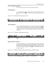
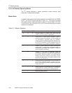
In slave mode, transmit and receive operations are controlled automatically by
the I
2
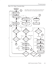
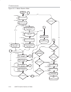
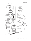
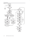
C module. The slave transmitter and slave receiver modes are shown in
Figure 15−11 and Figure 15−12.
In slave receiver mode, serial data bits received on SDA are shifted in with the
clock pulses that are generated by the master device. The slave device does
not generate the clock, but it can hold SCL low if intervention of the CPU is
required after a byte has been received. In slave receiver mode, every byte
received will be acknowledged. There is no way for a slave to generate a
NACK condition for received data.
Slave transmitter mode is entered when the slave address byte transmitted by
the master is the same as its own address and a set R/W
bit has been
transmitted indicating a request to send data to the master. The slave
transmitter shifts the serial data out on SDA with the clock pulses that are
generated by the master device. The slave device does not generate the clock,
but it will hold SCL low while intervention of the CPU is required after a byte
has been transmitted.
Note: I2CTRX Bit In Slave Mode
The I2CTRX bit must be cleared for proper slave mode operation.


