


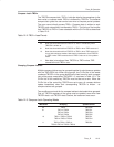
Timer_B Operation
12-9
Timer_B
Up/Down Mode
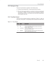
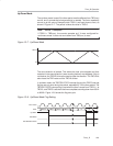
The up/down mode is used if the timer period must be different from TBR
(max)
counts, and if symmetrical pulse generation is needed. The timer repeatedly
counts up to the value of compare latch TBCL0, and back down to zero, as
shown in Figure 12−7. The period is twice the value in TBCL0.
Note: TBCL0 > TBR(max)
If TBCL0 > TBR
(max),
the counter operates as if it were configured for
continuous mode. It does not count down from TBR
(max)
to zero.
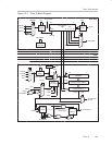
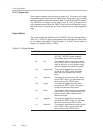
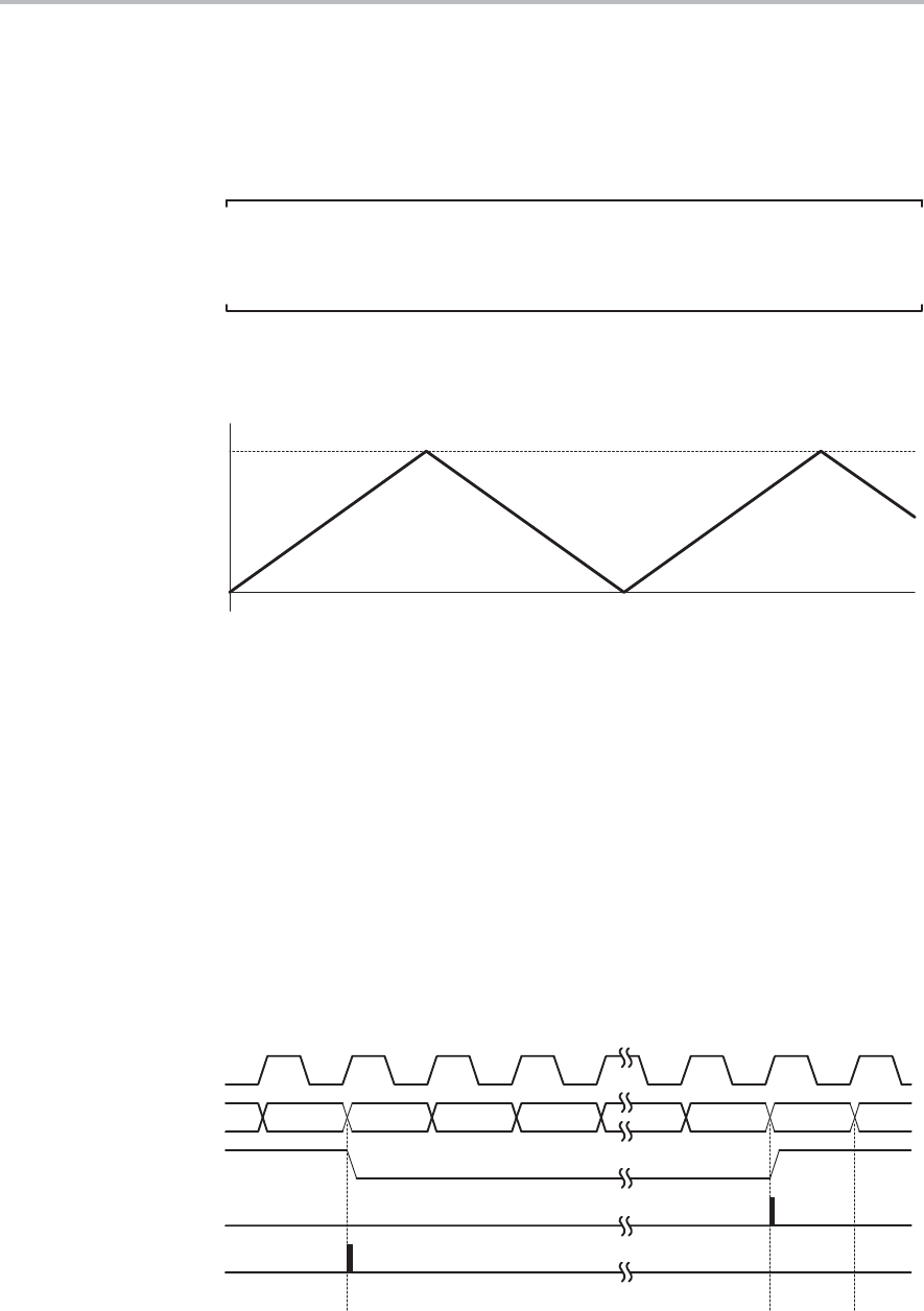
Figure 12−7. Up/Down Mode
0h
TBCL0
The count direction is latched. This allows the timer to be stopped and then
restarted in the same direction it was counting before it was stopped. If this is
not desired, the TBCLR bit must be used to clear the direction. The TBCLR bit
also clears the TBR value and the TBCLK divider.
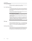
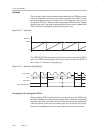
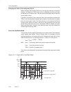
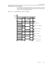
In up/down mode, the TBCCR0 CCIFG interrupt flag and the TBIFG interrupt
flag are set only once during the period, separated by 1/2 the timer period. The
TBCCR0 CCIFG interrupt flag is set when the timer counts from TBCL0−1 to
TBCL0, and TBIFG is set when the timer completes counting down from 0001h
to 0000h. Figure 12−8 shows the flag set cycle.
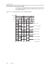
Figure 12−8. Up/Down Mode Flag Setting
TBCL0−1 TBCL0 TBCL0−1
Timer Clock
Timer
Set TBIFG
Set TBCCR0 CCIFG
TBCL0−2 1h 0h 1h
Up/Down