


Test Pattern File Formats FlexTest Test Pattern File Format
FastScan and FlexTest Reference Manual, V8.6_4
4-25
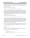
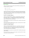
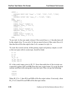
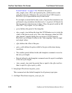
PI CLOCK
PI G3
PI G2
PI G1
PI G0
PO G17
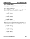
To create the data section, each line will correspond to one test cycle. For cycle =
0, we have:
FORCE “ibus” “10111” 0;
FORCE “ibus” “00111” 1;
MEASURE “obus_1” “1” 2;
Since CLOCK changes from 1 to 0 during the force of the input values, we assign
P to correspond to a positive pulse present during the test cycle. For the rest of the
input pins the values do not change, so it remains the same. We use the same
measure value for the output pin. Thus, we have the first line in the data section:
P01111
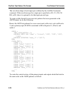
Looking at cycle=1 and the rest of the test cycles, we see that only CLOCK
changes values during the force of the input values and the rest remains the same.
This is because we specified CLOCK to have a pin constraint of R0. Thus, for the
rest of the lines in the data section, we have the following:
P00101
P00101
P10011
Since, we have a pin constraint for CLOCK (R0), we could have left out CLOCK
from the control section and the first column (P) in the data section. This is
because the system already knows that CLOCK will have a positive pulse every
test cycle specified with the Add Pin Constraints command.
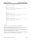
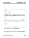
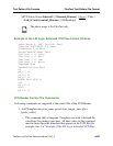
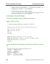
To create a table format that contains inout pins, we do the following:
Here is an ASCII patterns for a non-scan circuit that contains two tri-state devices
(The outputs of the tri-state are inout pins and both enable lines are connected
together):