


FastScan and FlexTest Reference Manual, V8.6_4
B-10
Using wdb2flex Effectively FlexTest WDB Translation Support
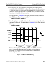
The following describes the corresponding wdb2flex control file. You can derive
this control file using the steps listed for obtaining an optimum control file.
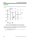
set cycle time 250
setup input strobes 75
setup output strobes 95
add input clocks SR0 105 205 CLK
You would issue the following FlexTest commands to specify a test cycle
consistent with this timing. You can derive this test cycle using the steps listed for
obtaining correspondence between the test cycle and the control file.
set test cycle 3
setup pIn constraints nr 1 0
setup pIn strobes 1
add pIn constraints clk sr0 1 1 1
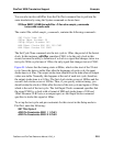
You can use the FlexTest commands for fault simulating the functional pattern
set. You can also invoke FlexTest ATPG on the faults not detected by the stimuli
in the waveform database. Finally, you can reproduce the same timing in any
simulation or ASIC vendor format by using the following timing file:
set force time 100 200 250
set bidi_force time 50 150 225 // for ABUS
set skew_force time “CNTRL” 70 170 230 // for CNTRL
set measure time 95 195 245
Despite all these precautions, there can still be mismatches between the expected
output values in QuickSim II and those in FlexTest. Some of the common causes
of mismatches are:
• Using unit delay simulation with QuickSim II. You should use typical delay
values whenever possible when performing QuickSim II simulations. Unit
delay simulation will give improper results for designs in which the clocks
of different latches and flip-flops have differing numbers of buffers feeding
them.
• Asynchronous loops in the design. If the design has asynchronous loops, set
loop handling to X in the FlexTest simulation. This causes FlexTest to
simulate more unknown values. However, this can potentially cause more
bus contention.