


FastScan and FlexTest Reference Manual, V8.6_4
B-8
Using wdb2flex Effectively FlexTest WDB Translation Support
• wdb2flex resolves the state of bidirectional pins as either input or output
based on the state of the forces and results waveform associated with the
pin. If the forces waveform has a weak strength, the bidirectional is treated
as an output. If the results waveform has a weak strength, the bidirectional
is treated as an input. If neither forces nor results waveforms have a weak
strength and have the same logic values, the utility assumes wired behavior
and treats the bidirectional as an output. If none of the above conditions
prevail, the bidirectional is neither measured nor driven.
To ensure that the results of a QuickSim II simulation correspond with that of
FlexTest, the FlexTest test cycle should correspond to the wdb2flex control file.
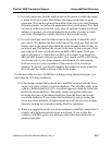
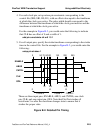
You can set up the test cycle using the following steps and the example timing
illustration in Figure B-2:
1. Calculate the number of timeframes in the FlexTest test cycle. The number
should equal the sum of the control file input strobe times and clock strobe
times.
For the example in Figure B-2, if all inputs strobe at 75ns (time t1), all
clocks strobe active at 105ns (time t2), and all clocks strobe for the off-state
at 205ns (time t3), then there should be three timeframes in the test cycle.
The first timeframe (frame 0) corresponds to the time 0—105ns (t1,t2), the
second timeframe (frame 1) corresponds to the time 105—205ns (t2,t3) and
the third timeframe (frame 2) corresponds to the time 205—250ns (t3,
period). The time from 0—75ns is not considered since the stable output is
strobed at 95ns and all input events happen before 75ns.
2. Calculate the timeframe associated with each strobe time. In FlexTest,
when a force event and strobe event occur in the same timeframe, the strobe
event happens before the force event in that timeframe.
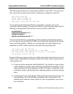
3. For all input pins, set up non-return pin constraints with an offset value
equal to one less than the timeframe at which the pin changes state. For the
example in Figure B-2, you would enter the following to indicate that the
offset value is 0; all inputs change at the first timeframe:
setup pin constraints nr 1 0