TMP92CM22
2007-02-16
92CM22-102
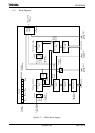
3.7.2 Operation of Each Circuit
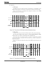
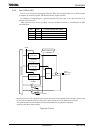
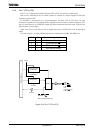
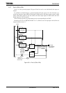
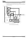
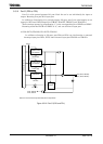
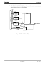
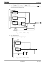
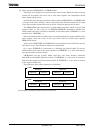
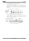
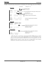
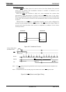
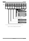
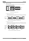
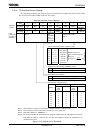
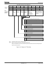
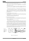
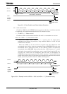
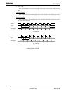
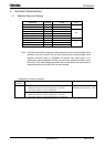
(1) Prescaler
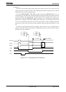
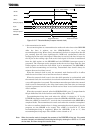
A 9-bit prescaler generates the input clock to TMRA01.
The prescaler’s operation can be controlled using TA01RUN<TA0PRUN> in the
timer control register. Setting <TA0PRUN> to “1” starts the count; setting
<TA0PRUN> to “0” clears the prescaler to “0” and stops operation.
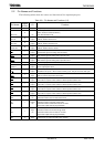
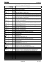
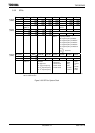
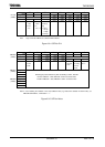
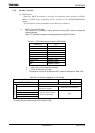
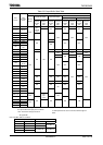
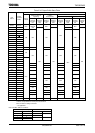
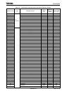
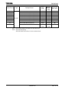
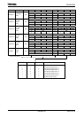
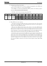
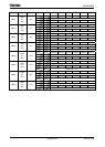
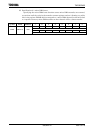
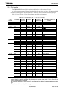
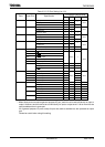
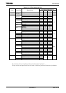
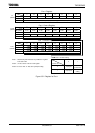
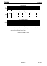
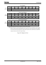
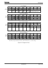
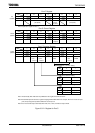
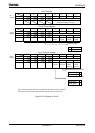
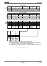
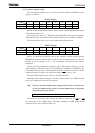
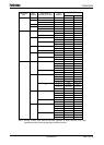
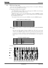
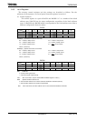
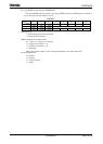
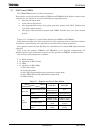
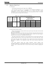
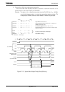
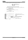
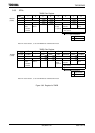
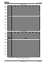
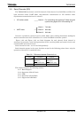
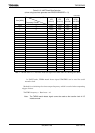
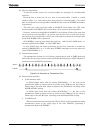
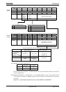
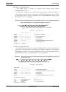
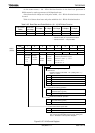
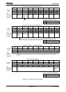
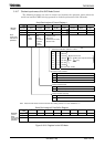
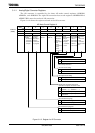
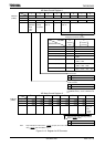
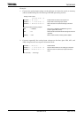
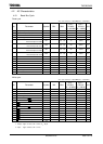
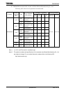
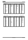
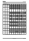
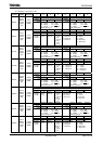
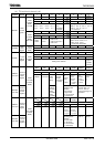
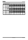
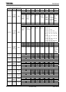
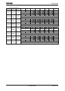
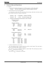
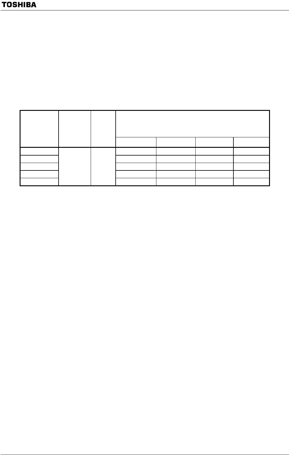
Table 3.7.2 shows
the various prescaler output clock resolutions.
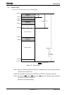
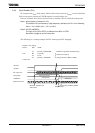
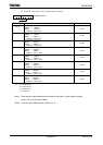
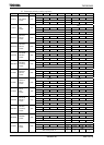
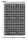
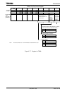
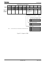
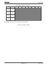
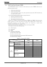
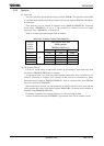
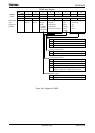
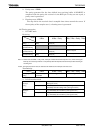
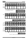
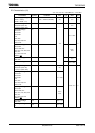
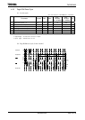
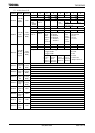
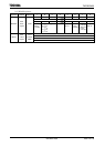
Table 3.7.2 Prescaler Output Clock Resolution
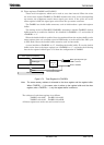
Timer counter input clock
TMRA prescaler
TAxMOD<TAxCLK1:0>
Clock gear
selection
SYSCR1
<GEAR2:0>
System clock
selection
SYSCR1
<SYSCK>
−
φT1(1/2) φT4(1/8) φT16(1/32) φT256(1/512)
000 (1/1) fc/16 fc/64 fc/256 fc/4096
001 (1/2) fc/32 fc/128 fc/512 fc/8192
010 (1/4) fc/64 fc/256 fc/1024 fc/16384
011 (1/8) fc/128 fc/512 fc/2048 fc/32768
100 (1/16)
0 (fc) 1/8
fc/256 fc/1024 fc/4096 fc/65536
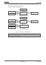
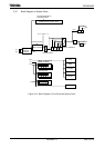
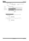
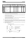
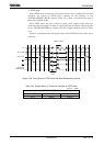
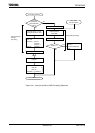
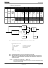
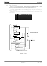
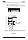
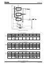
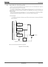
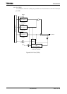
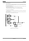
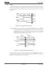
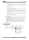
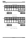
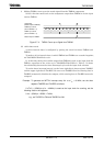
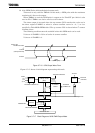
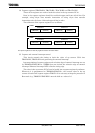
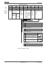
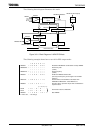
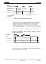
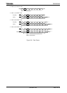
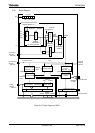
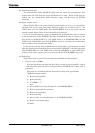
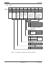
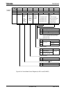
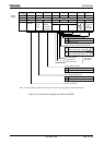
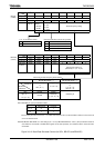
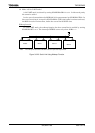
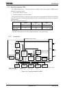
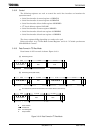
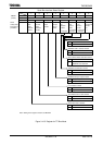
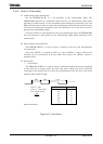
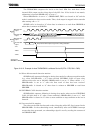
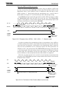
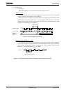
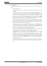
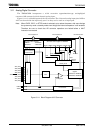
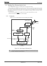
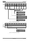
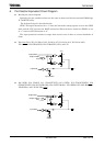
(2) Up counters (UC0 and UC1)
These are 8-bit binary counters which count up the input clock pulses for the clock
specified by TA01MOD.
The input clock for UC0 is selectable and can be either the external clock input via the
TA0IN pin or one of the three internal clocks φT1, φT4, or φT16. The clock setting is
specified by the value set in TA01MOD<TA01CLK1:0>.
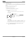
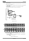
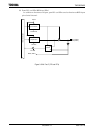
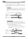
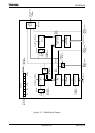
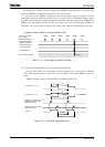
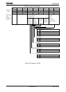
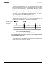
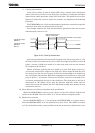
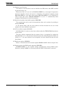
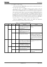
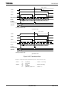
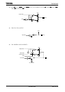
The input clock for UC1 depends on the operation mode. In 16-bit timer mode, the
overflow output from UC0 is used as the input clock. In any mode other than 16-bit
timer mode, the input clock is selectable and can either be one of the internal clocks
φT1, φT16, or φT256, or the comparator output (The match detection signal) from
TMRA0.
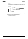
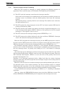
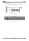
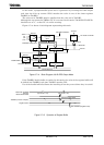
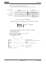
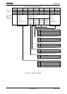
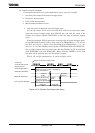
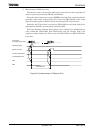
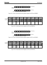
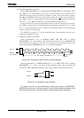
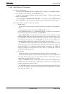
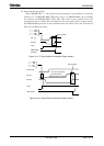
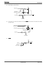
For each interval timer the timer operation control register bits
TA01RUN<TA0RUN> and TA01RUN<TA1RUN> can be used to stop and clear the up
counters and to control their count. A reset release both up counters, stopping the
timers.