


TMP92CM22
2007-02-16
92CM22-202
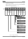
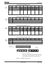
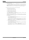
AD Conversion Result Register 0 Low
7 6 5 4 3 2 1 0
Bit symbol ADR01 ADR00 ADR0RFADREG0L
(12A0H)
Read/Write R R
After reset Undefined 0
Function Stores lower 2 bits of AD
conversion result
AD conversion
data storage
flag
1: Conversion
result stored
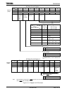
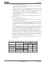
AD Conversion Result Register 0 High
7 6 5 4 3 2 1 0
Bit symbol ADR09 ADR08 ADR07 ADR06 ADR05 ADR04 ADR03 ADR02 ADREG0H
(12A1H)
Read/Write R
After reset Undefined
Function Stores upper 8 bits AD conversion result.
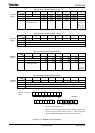
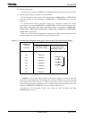
AD Conversion Result Register 1 Low
7 6 5 4 3 2 1 0
Bit symbol ADR11 ADR10 ADR1RFADREG1L
(12A2H)
Read/Write R R
After reset Undefined 0
Function Stores lower 2 bits of AD
conversion result
AD conversion
data storage
flag
1: Conversion
result stored
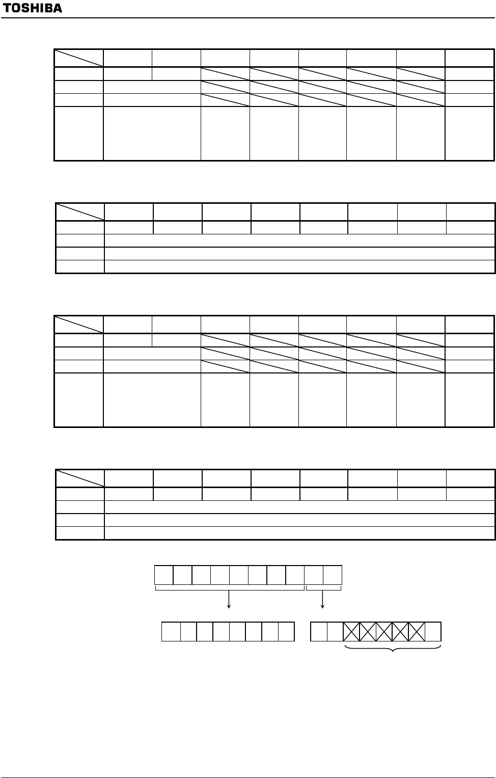
AD Conversion Result Register 1 High
7 6 5 4 3 2 1 0
Bit symbol ADR19 ADR18 ADR17 ADR16 ADR15 ADR14 ADR13 ADR12 ADREG1H
(12A3H)
Read/Write R
After reset Undefined
Function Stores upper 8 bits of AD conversion result.
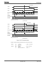
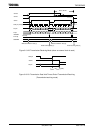
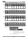
9 8 76543210
7 6 543210 76543 2 1 0
Figure 3.11.4 Register for AD Converter
Channel x
conversion result
A
DREGxL
• Bits 5 to 1 are always read as 1.
• Bit0 is the AD conversion data storage flag <ADRxRF>. When the AD
conversion result is stored, the flag is set to 1. When either of the
registers (ADREGxH, ADREGxL) is read, the flag is cleared to 0.
A
DREGxH