TMP92CM22
2007-02-16
92CM22-123
3.8.2 Operation
(1) Prescaler
The 5-bit prescaler generates the source clock for TMRB0. The prescaler clock (φT0)
is a divided clock (Divided by 8) from selected clock by the register SYSCR1<GEAR1:0>
of clock gear.
This prescaler can be started or stopped using TB0RUN<TB0PRUN>. Counting
starts when <TB0PRUN> is set to 1; the prescaler is cleared to zero and stops
operation when <TB0PRUN> is cleared to 0.
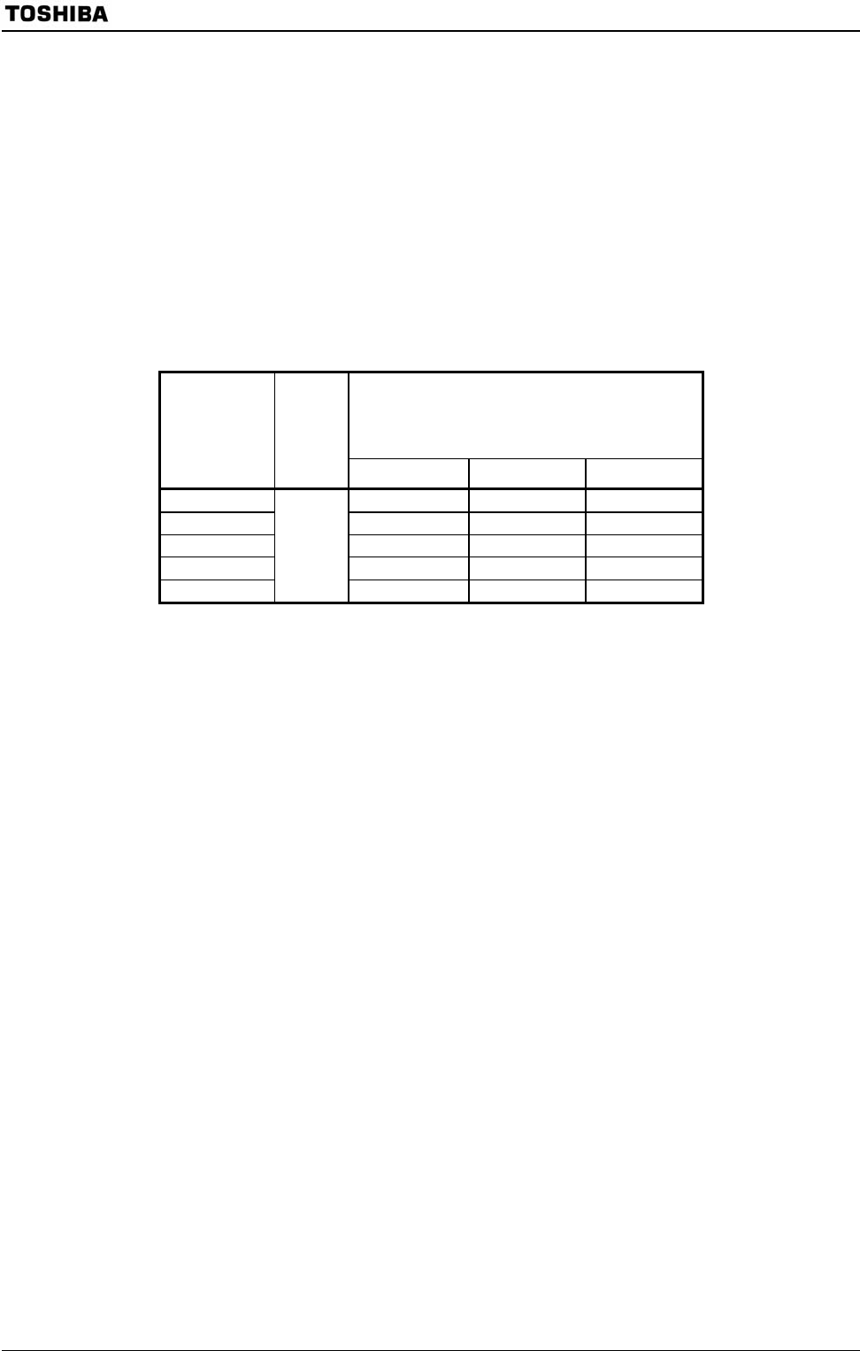
Table 3.8.2 show prescaler output clock resolution.
Table 3.8.2 Prescaler Output Clock Resolution
Timer counter input clock
TMRB prescaler
TB0MOD<TB0CLK1:0>
Clock gear
selection
SYSCR1
<GEAR2:0>
−
φT1(1/2) φT4 (1/8) φT16 (1/32)
000 (1/1) fc/16 fc/64 fc/256
001 (1/2) fc/32 fc/128 fc/512
010 (1/4) fc/64 fc/256 fc/1024
011 (1/8) fc/128 fc/512 fc/2048
100 (1/16)
1/8
fc/256 fc/1024 fc/4096
(2) Up counter (UC10)
UC10 is a 16-bit binary counter that counts up according to input from the clock
specified by TB0MOD<TB0CLK1:0> register.
As the input clock, one of the prescaler internal clocks φT1, φT4, and φT16 can be
selected. Counting or stopping and clearing of the counter is controlled by timer
operation control register TB0RUN<TB0RUN>. And an external clock from TB1IN0
pin can be selected in TB1MOD.
When clearing is enabled, the up counter UC10 will be cleared to zero each time its
value matches the value in the timer register TB0RG1H/L. Clearing can be enabled or
disabled using TB0MOD<TB0CLE>.
If clearing is disabled, the counter operates as a free-running counter.
A timer overflow interrupt (INTTBOF0) is generated when UC10 overflow occurs.


