


TMP92CM22
2007-02-16
92CM22-225
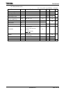
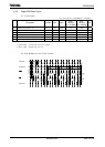
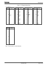
4.6 Interrupt, Capture
Note: Symbol “X” in the following table means the period of clock “f
SYS
”, it’s same period of the system
clock “f
SYS
” for CPU core. The period of f
SYS
depends on the clock gear setting or changing
high-speed oscillator/low-speed oscillator and so on.
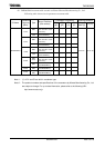
(1)
NMI and INT0 to INT3 interrupts
Variable
f
SYS
=
20 MHz
(fc = 40 MHz)
f
SYS
=
125 kHz
(fc = 4 MHz)
Parameter Symbol
Min Max Min Max Min Max
Unit
INT0 to INT3 low width T
INTAL
4X + 40 240 32040
INT0 to INT3 high width T
INTAH
4X + 40 240 32040
ns
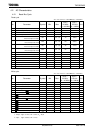
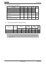
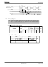
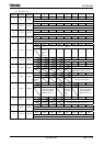
(2) INT4 to INT5 interrupts
t
INTBL
(INT4 to INT5 Low Level Pulse Width)
t
INTBH
(INT4 to INT5 High Level Pulse Width)
Variable
f
SYS
= 20 MHz
(fc = 40 MHz)
Variable
f
SYS
= 20 MHz
(fc = 40 MHz)
Min Min Min
Min
Unit
8X + 100 500 8X + 100
500 ns
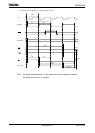
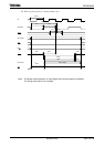
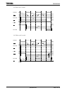
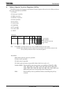
Valid
3
2
SCLK
Output mode/
in
p
ut risin
g
mode
0 1 2
SCLK
(Input falling mode)
Output data
TXD
Input data
RXD
t
SC
Y
t
OSS
t
OHS
t
SRD
t
RDS
t
HSR
Valid Valid Valid
3 1 0