


TMP92CM22
2007-02-16
92CM22-207
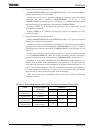
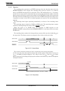
(3) Starting AD conversion
To start AD conversion, program “1” to ADMOD0<ADS> in AD mode control register
0, or ADMOD1<ADTRGE> in AD mode control register 1 and input falling edge on
ADTRG pin. When AD conversion starts, the AD conversion busy flag
ADMOD0<ADBF> will be set to “1”, indicating that AD conversion is in progress.
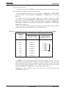
(4) AD conversion modes and the AD conversion end interrupt
The four AD conversion modes are:
• Channel fixed single conversion mode
• Channel scan single conversion mode
• Channel fixed repeat conversion mode
• Channel scan repeat conversion mode
The ADMOD0<REPEAT> and ADMOD0<SCAN> settings in AD mode control
register 0 determine the AD mode setting.
Completion of AD conversion triggers an INTAD AD conversion end interrupt
request. Also, ADMOD0<EOCF> will be set to 1 to indicate that AD conversion has
been completed.
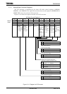
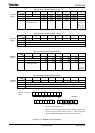
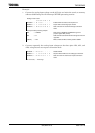
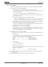
1. Channel fixed single conversion mode
Setting ADMOD0<REPEAT> and ADMOD0<SCAN> to “00” selects conversion
channel fixed single conversion mode.
In this mode data on one specified channel is converted once only. When the
conversion has been completed, the ADMOD0<EOCF> flag is set to 1,
ADMOD0<ADBF> is cleared to “0”, and an INTAD interrupt request is generated.
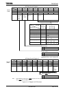
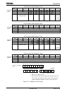
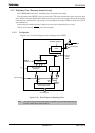
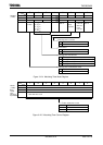
2. Channel scan single conversion mode
Setting ADMOD0<REPEAT> and ADMOD0<SCAN> to “01” selects conversion
channel scan single conversion mode.
In this mode data on the specified scan channels is converted once only. When
scan conversion has been completed, ADMOD0<EOCF> is set to “1”,
ADMOD0<ADBF> is cleared to “0”, and an INTAD interrupt request is generated.