TMP92CM22
2007-02-16
92CM22-125
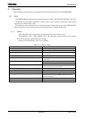
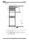
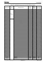
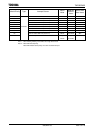
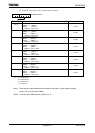
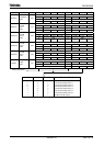
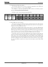
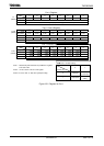
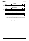
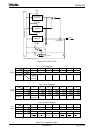
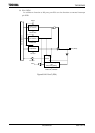
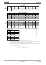
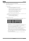
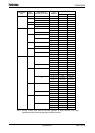
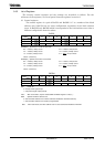
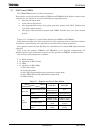
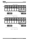
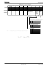
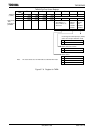
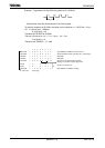
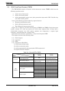
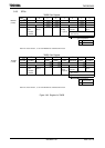
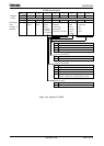
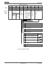
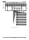
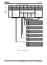
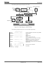
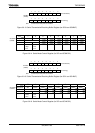
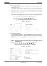
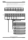
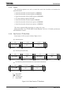
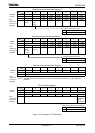
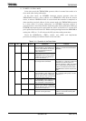
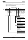
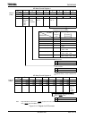
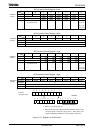
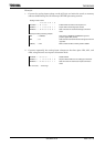
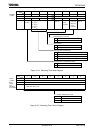
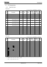
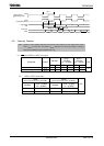
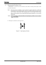
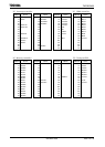
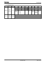
(4) Capture registers (TB0CP0H/L, TB0CP1H/L, TB1CP0H/L and TB1CP1H/L)
These 16-bit registers are used to latch the values in the up counters UC10.
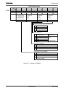
Data in the capture registers should be read both upper and lower all 16 bits. For
example, using 2-byte data transfer instruction or using 1-byte data transfer
instruction twice for lower 8 bits and upper 8 bits in order.
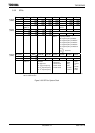
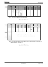
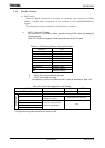
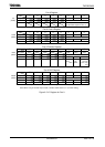
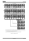
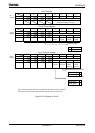
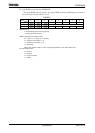
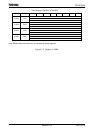
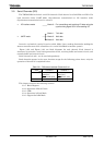
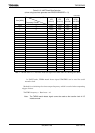
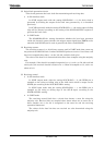
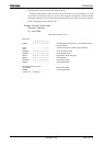
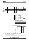
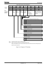
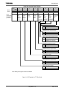
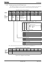
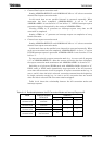
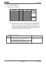
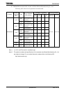
The addresses of the capture registers are as follows:
The capture registers are read-only registers and thus cannot be written.
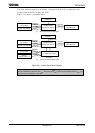
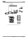
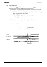
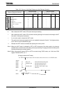
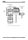
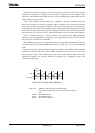
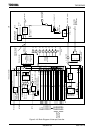
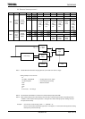
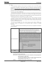
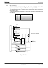
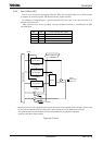
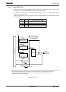
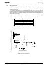
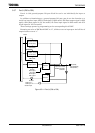
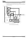
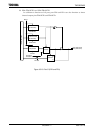
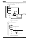
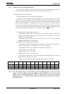
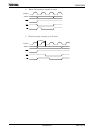
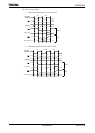
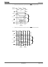
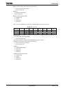
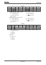
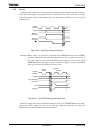
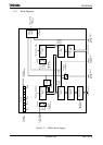
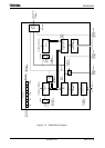
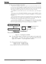
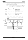
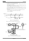
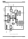
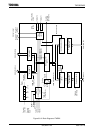
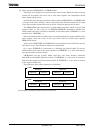
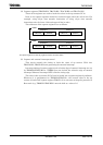
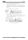
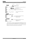
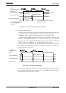
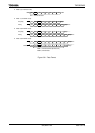
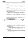
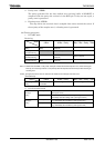
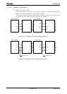
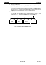
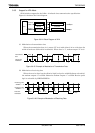
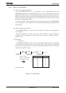
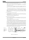
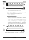
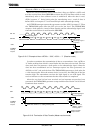
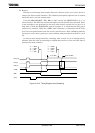
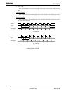
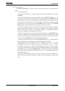
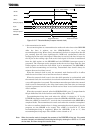
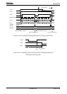
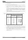
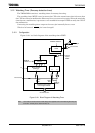
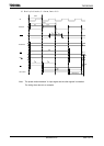
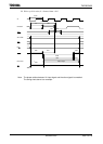
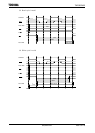
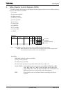
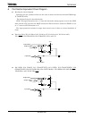
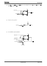
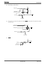
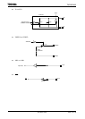
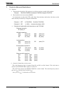
(5) Capture and external interrupt control
This circuit controls the timing to latch the value of up counter UC10 into
TB0CP0H/L, TB0CP1H/L and generating for external interrupt.
Interrupt timing of capture register and selection edge of external interrupt are set
by TB0MOD<TB0CPM1:0>. (TMRB0 does not include the selection edge of external
interrupt.) External interrupt INT5 is fixed to rising edge.
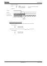
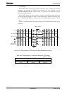
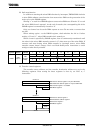
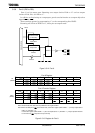
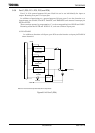
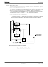
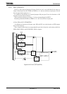
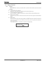
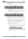
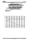
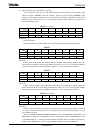
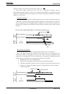
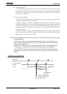
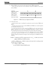
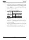
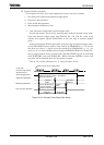
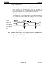
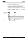
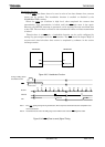
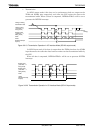
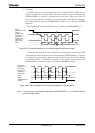
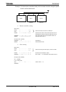
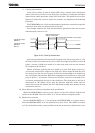
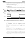
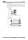
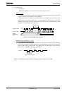
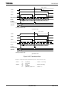
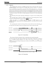
The value in the up counter (UC10) can be loaded into a capture register by software.
Whenever 0 is programmed to TB0MOD<TB0CP0I>, the current value in the up
counter is loaded into capture register TB0CP0. It is necessary to keep the prescaler in
Run mode (e.g., TB0RUN<TB0PRUN> must be held at a value of 1).
TMRB0
118DH 118CH 118FH 118EH
TB0CP0H/L TB0CP1H/L
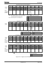
Upper 8 bits
(TB0CP0H)
Lower 8 bits
(TB0CP0L)
TMRB1
119DH 119CH 119FH 119EH
TB1CP0H/L TB1CP1H/L
Upper 8 bits
(TB0CP1H)
Lower 8 bits
(TB0CP1L)
Upper 8 bits
(TB1CP1H)
Lower 8 bits
(TB1CP1L)
Upper 8 bits
(TB1CP0H)
Lower 8 bits
(TB1CP0L)