


TMP92CM22
2007-02-16
92CM22-22
3.3.6 Standby Controller
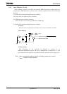
(1) HALT modes
When the HALT instruction is executed, the operating mode switches to IDLE2,
IDLE1, or STOP mode, depending on the contents of the SYSCR2<HALTM1:0>
register.
The subsequent actions performed in each mode are as follows:
a. IDLE2: Only the CPU halts.
The internal I/O is available to select operation during IDLE2 mode by setting the
following register.
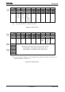
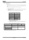
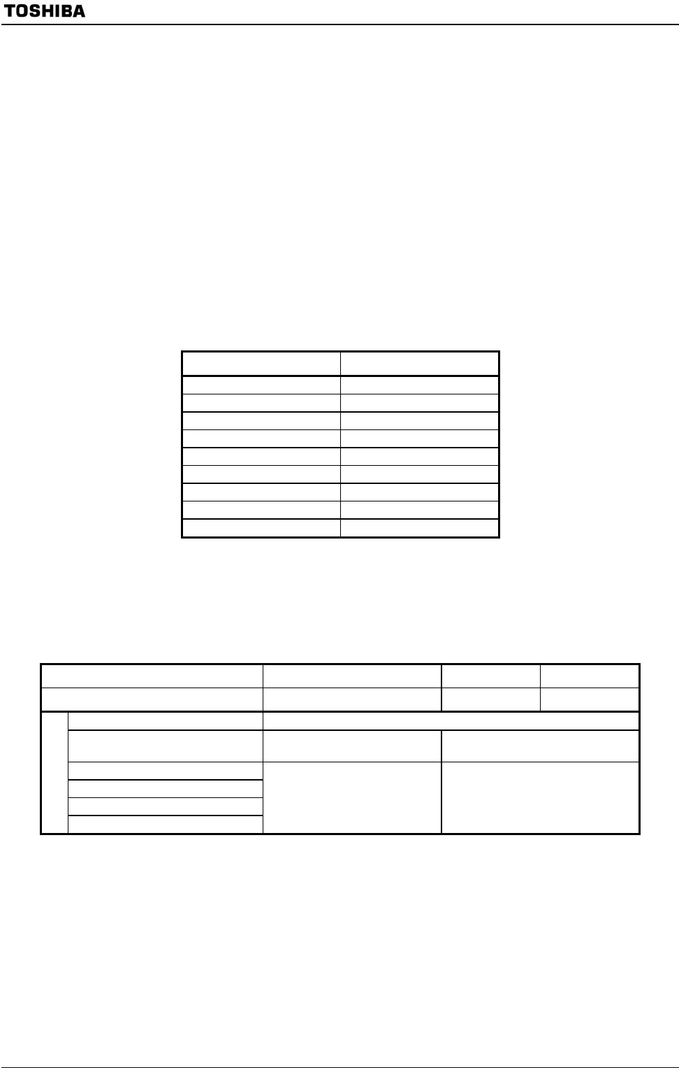
Table 3.3.1 shows the registers of setting operation during IDLE2 mode.
Table 3.3.1 SFR Seting Operation during IDLE2 Mode
Internal I/O SFR
TMRA01 TA01RUN<I2TA01>
TMRA23 TA23RUN<I2TA23>
TMRB0 TB0RUN<I2TB0>
TMRB1 TB1RUN<I2TB1>
SIO0 SC0MOD1<I2S0>
SIO1 SC1MOD1<I2S1>
AD converter ADMOD1<I2AD>
WDT WDMOD<I2WDT>
SBI SBI0BR0<I2SBI0>
b. IDLE1: Only internal oscillator operates.
c. STOP: All internal circuit stop.
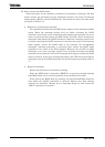
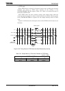
The operation of each of the different HALT modes is described in
Table 3.3.2.
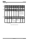
Table 3.3.2 Each Block Operation in HALT Mode
HALT Mode IDLE2 IDLE1 STOP
SYSCR2<HALTM1:0> 11 10 01
CPU Stop
I/O port Keep the state when the HALT
instruction is executed.
Refer
Table 3.3.5, Table 3.3.6
TMRA, TMRB
SIO, *SBI
AD converter
Operation block
WDT
* Selection enable operation
block to programmable
Stop
*: Except clocked-synchronous 8-bit SIO mode for SBI.