TMP92CM22
2007-02-16
92CM22-185
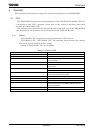
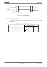
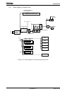
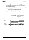
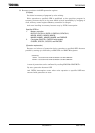
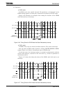
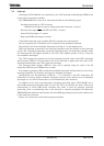
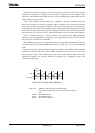
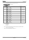
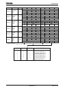
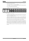
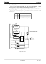
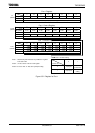
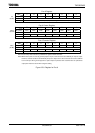
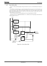
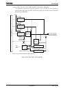
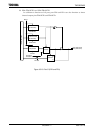
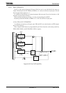
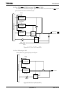
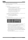
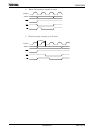
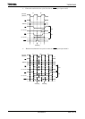
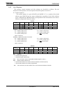
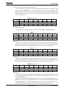
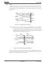
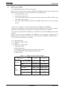
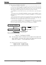
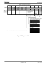
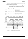
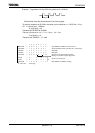
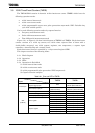
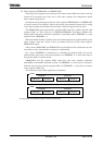
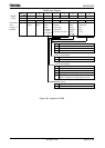
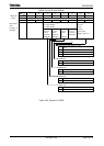
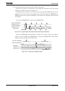
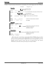
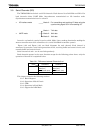
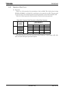
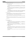
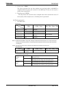
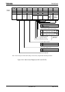
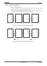
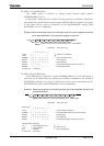
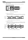
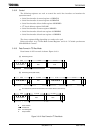
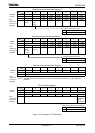
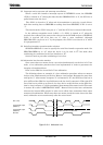
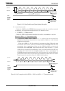
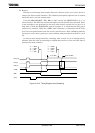
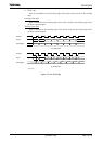
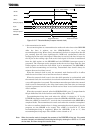
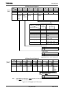
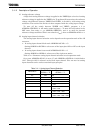
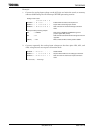
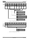
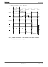
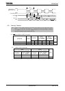
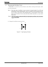
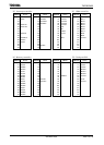
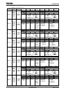
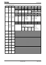
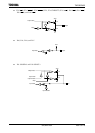
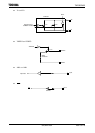
Figure 3.10.13 Start Condition and Slave Address Generation
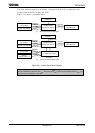
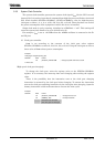
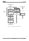
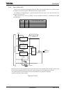
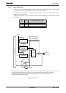
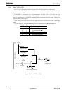
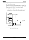
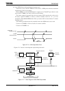
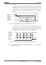
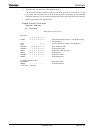
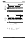
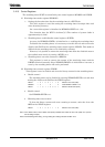
(3) 1-word data transfer
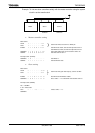
Check the <MST> by the INTSBE0 interrupt process after the 1-word data transfer
is completed, and determine whether the mode is a master or slave.
1. If <MST> = “1” (Master mode)
Check the <TRX> and determine whether the mode is a transmitter or receiver.
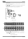
When the <TRX> = “1” (Transmitter mode)
Check the <LRB>. When <LRB> is “1”, a receiver does not request data.
Implement the process to generate a stop condition (Refer to
3.10.6 (4)) and
terminate data transfer.
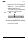
When the <LRB> is “0”, the receiver is requests new data. When the next
transmitted data is 8 bits, write the transmitted data to SBI0DBR. When the next
transmitted data is other than 8 bits, set the <BC2:0> <ACK> and write the
transmitted data to SBI0DBR. After written the data, <PIN> becomes “1”, a serial
clock pulse is generated for transferring a new 1-word of data from the SCL pin,
and then the 1-word data is transmitted. After the data is transmitted, an
INTSBE interrupt request generates. The <PIN> becomes “0” and the SCL line is
pulled down to the low level. If the data to be transferred is more than one word in
length, repeat the procedure from the <LRB> checking above.
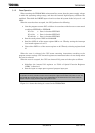
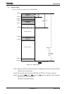
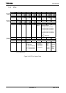
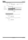
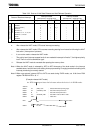
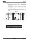
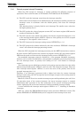
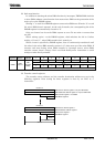
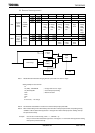
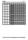
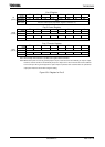
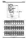
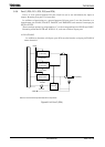
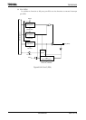
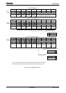
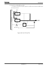
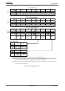
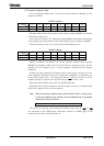
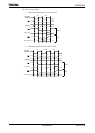
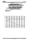
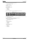
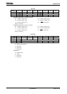
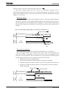
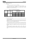
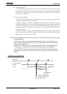
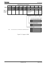
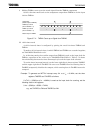
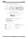
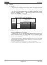
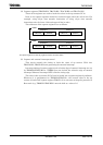
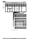
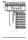
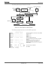
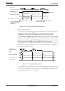
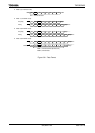
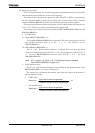
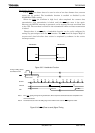
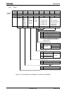
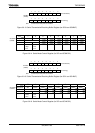
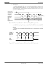
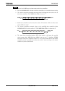
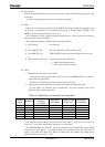
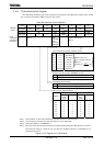
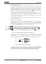
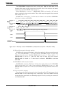
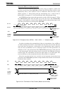
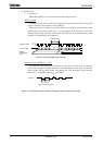
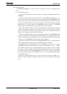
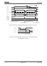
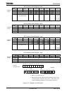
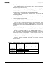
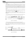
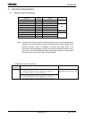
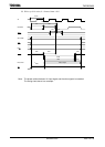
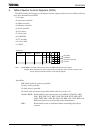
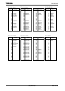
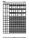
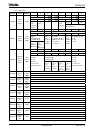
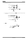
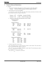
Figure 3.10.14 Example in which <BC2:0> = “000” and <ACK> = “1” (Transmitter mode)
1 2 345678 9
D7 D6 D5 D4 D3 D2 D1 D0
cknowledge signal
from a receive
Write to SBI0DBR
SCL Pin
SDA Pin
<PIN>
INTSBE0
interrupt
request
ACK
Output of master
Output of slave
1
2 345678 9
A6 A5 A4 A3 A2 A1 A0 R/
W
Slave address
Direction bit
cknowledge
signal from a
slave device
Start condition
SCL line
SDA line
<PIN>
INTSBE0
interrupt
request
Output of master
Output of slave
ACK