


TMP92CM22
2007-02-16
92CM22-244
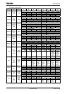
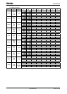
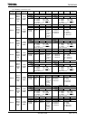
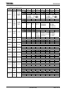
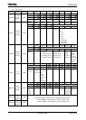
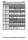
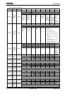
(8) UART/Serial channel (1/2)
Symbol Name
Address 7 6 5 4 3 2 1 0
RB7
TB7
RB6
TB6
RB5
TB5
RB4
TB4
RB3
TB3
RB2
TB2
RB1
TB1
RB0
TB0
R(Receiving) / W(Transmission)
SC0BUF
Serial
channel 0
buffer
register
1200H
(Prohibit
RMW)
Undefined
RB8 EVEN PE OERR PERR FERR SCLKS IOC
R R/W R (Clear o after reading) R/W
Undefined 0 0 0 0 0 0 0
1: Error
SC0CR
Serial
channel 0
control
register
1201H
Receive
data
bit8
Parity
0: Odd
1: Even
Parity
0: Disable
1: Enable
Overrun Parity Framing
0: SCLK0↑
1: SCLK0↓
0: Baud
rate
generator
1: SCLK0 pin
input
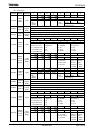
TB8 CTSE RXE WU SM1 SM0 SC1 SC0
R/W
0 0 0 0 0 0 0 0
SC0MOD0
Serial
channel 0
mode 0
register
1202H
Transmis-
sion data
bit8
0: CTS
disable
1: CTS
enable
0: Receive
disable
1: Receive
enable
Wake up
0: Disable
1: Enable
00: I /O interface mod
e
01: 7-bit UART mode
10: 8-bit UART mode
11: 9-bit UART mode
00: Timer TA0REG
01: Baud rate
generator
10: Internal clock fio
11: External clock
(SCLK0 input)
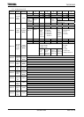
− BR0ADDE BR0CK1 BR0CK0 BR0S3 BR0S2 BR0S1 BR0S0
R/W
0 0 0 0 0 0 0 0
BR0CR
Serial
channel 0
baud rate
control
register
1203H
Always
write “0”.
(16 − K)/
16 divided
0: Disable
1: Enable
00: φT0
01: φT2
10: φT8
11: φT32
Divided frequency setting
BR0K3 BR0K2 BR0K1 BR0K0
R/W
0 0 0 0
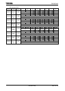
BR0ADD
Serial
channel 0
K setting
register
1204H
Sets frequency divisor “K”
(divided by N + (16 − K)/16).
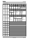
I2S0 FDPX0
R/W
0 0
SC0MOD1
Serial
channel 0
mode 1
register
1205H
IDLE2
0: Stop
1: Operate
I/O interface
mode
0: Half duplex
1: Full duplex
PLSEL RXSEL TXEN RXEN SIRWD3 SIRWD2 SIRWD1 SIRWD0
R/W
0 0 0 0 0 0 0 0
SIRCR
IrDA
control
register
1207H
Select
transmit
pulse
width
0: 3/16
1: 1/16
Receive
data
0: “H” pulse
1: “L” pulse
Transmit
0: Disable
1: Enable
Receive
0: Disable
1: Enable
Select receive pulse width
Set effective pulse width for equal or more
than 2x × (Value + 1) + 100 ns
Can be set: 1 to 14
Can not be set: 0, 15