


TMP92CM22
2007-02-16
92CM22-24
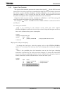
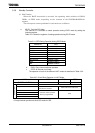
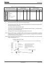
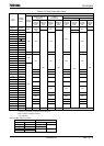
Table 3.3.3 Source of Halt State Release and Halt Release Operation
Status of Received Interrupt
Interrupt Enable
(Interrupt level) ≥ (Interrupt mask)
Interrupt Disable
(Interrupt level) < (Interrupt mask)
HALT Mode Programmable IDLE2 IDLE1 STOP Programmable IDLE2 IDLE1 STOP
Interrupt
NMI
INTWDT
INT0 to 3 (Note1)
INT4 to 5
INTTA0 to 3,
INTTB00, 01, 10, 11, O0, O1
INTRX0 to 1, TX0 to 1
INTAD
INTSBE0
♦
♦
♦
♦
♦
♦
♦
♦
♦
♦
×
♦
×
×
×
×
×
×
♦
×
♦*1
×
×
×
×
×
×
−
−
○
×
×
×
×
×
×
−
−
○
×
×
×
×
×
×
−
−
○*1
×
×
×
×
×
×
Source of HALT state release
Reset Initialize LSI
♦: After release the HALT mode, CPU starts interrupt processing.
○: After release the HALT mode, CPU resumes executing starting from instruction following the HALT
instruction. (Interrupt don’t process.)
×: It can not be used to release the HALT mode.
−: The priority level (Interrupt request level) of non-maskable interrupts is fixed to 7, the highest priority
level. There is not this combination type.
*1: Release the HALT mode is executed after passing the warm-up time.
Note 1: When the HALT mode is released by INT0 to INT3 interrupts of the level mode in the interrupt
enabled status, hold this level until starting interrupt processing. Changing level before holding level,
interrupt processing is correctly started.
Note 2: When use external interrupt INT4 to INT5 are used during IDLE2 mode, set 16-bit timer RUN
register TB1RUN<I2TB1> to “1”.
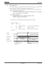
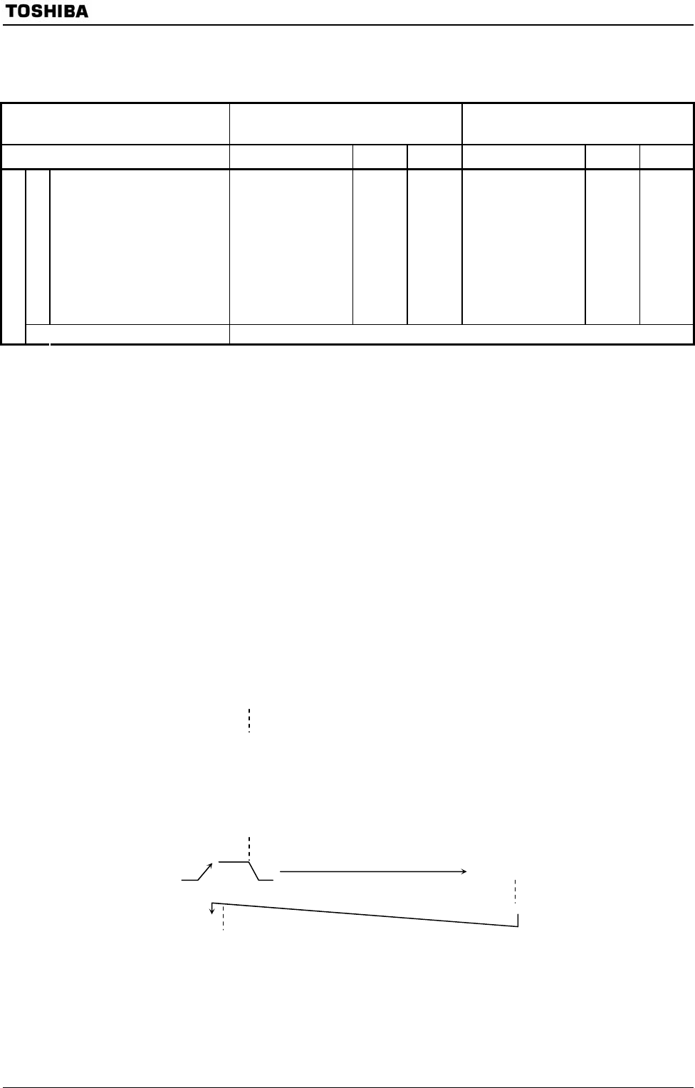
(Example release HALT mode)
An INT0 interrupt release the halt state when the device is in IDLE1 mode.
Address
8203H LD (IIMC), 00H ; Selects INT0 interrupt rising edge.
8206H LD (INTE0AD), 06H ; Sets INT0 interrupt level to 6.
8209H EI 5 ; Sets CPU interrupt level to 5.
820BH LD (SYSCR2), 28H ; Sets HALT mode to IDLE1 mode.
820EH HALT ; Halts CPU.
INT0 INT0 interrupt routine
RETI
820FH LD XX, XX