


TMP92CM22
2007-02-16
92CM22-27
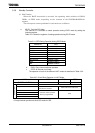
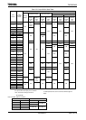
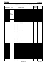
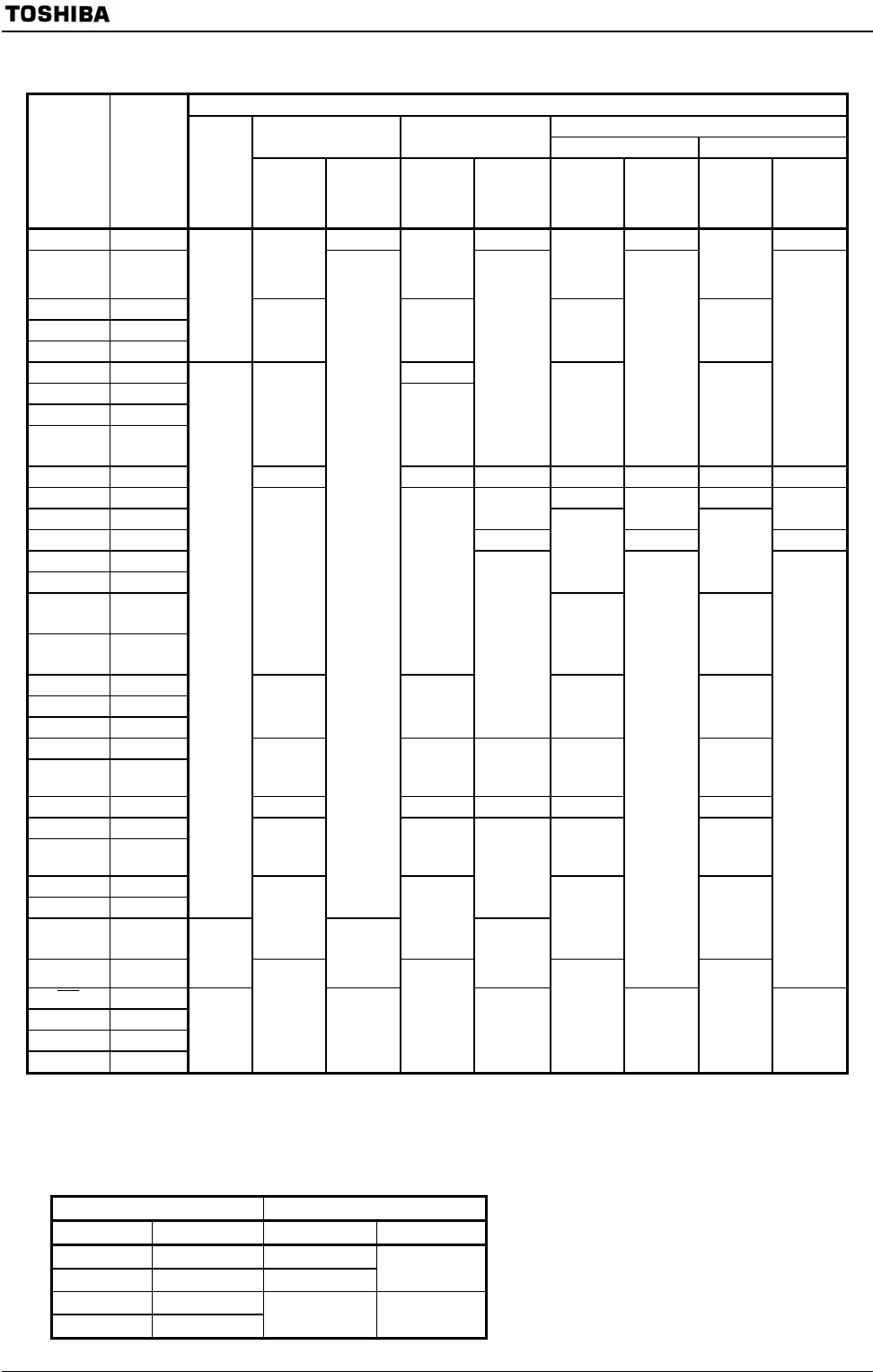
Table 3.3.5 Input Buffer State Table
Input Buffer State
In HALT mode (IDLE1/STOP)
Input Buffer State Input Buffer State
Condition A (Note) Condition B (Note)
Port
Name
Input
Function
Name
During
Reset
When
Used as
function
Pin
When
Used as
Input
Port
When
Used as
function
Pin
When
Used as
Input
Port
When
Used as
function
Pin
When
Used as
Input
Port
When
Used as
function
Pin
When
Used as
Input
Port
D0-D7 D0-D7 − − − −
P10-P17 D8-D15
ON
upon
external
read
OFF OFF OFF
P40-P47 −
P50-P57 −
P60-P67 −
OFF
− − − −
P76 WAIT OFF
P90 SCK
P91 SDA
P92
SI
SCL
ON
ON
OFF
OFF
OFF
OFF
OFF
PA0-PA7(*1) − − − ON − ON − ON
PC0 TA0IN OFF OFF
PC1 INT1
OFF OFF OFF
PC3 INT0 ON ON ON
PC5 INT2
PC6 INT3
ON ON
PD0
INT4,
TB1IN0
PD1
INT5,
TB1IN1
ON ON
OFF OFF
PD2 −
PD3 −
PF0 −
− −
OFF
− −
PF1 RXD0
PF2
SCLK0,
CTS0
ON ON ON OFF OFF
PF3 − − − OFF − −
PF4 RXD1
PF5
SCLK1,
CTS1
ON ON OFF OFF
PF6 −
PF7 −
ON
ON
ON
PG0-2,
PG4-7(*2)
−
− − − −
PG3(*2) ADTRG
OFF
ON
upon
port
read
OFF
OFF OFF
NMI
−
RESET(*1) −
AM0,1 −
X1
ON
ON
−
ON
−
ON
−
ON
−
ON: The buffer is always turned on. A current flows
the input buffer if the input pin is not driven.
*1: Port having a pull-up/pull-down resistor.
OFF: The buffer is always turned off.
*2: AIN input does not cause a current to flow through the
buffer.
−: No applicable
Note: Condition A/B are as follows.
SYSCR2 register setting HALT mode
<DRVE> <SELDRV> IDLE1 STOP
0 0 Condition B
0 1 Condition A
Condition A
1 0
1 1
Condition B Condition B