


TMP92CM22
2007-02-16
92CM22-94
(1) Block address area specification register
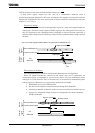
A start address and range in the block address are specified by the memory start
address register (MSARn) and the memory address mask register (MAMRn). The
memory start address register sets all start address similarly regardless of the block
address areas. The bit to be set by the memory address mask register is depended on
the block address area.
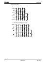
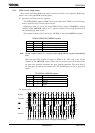
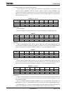
MSARn (n = 0 to 3)
7 6 5 4 3 2 1 0
Bit symbol MnS23 MnS22 MnS21 MnS20 MnS19 MnS18 MnS17 MnS16
Read/Write R/W
After reset 1 1 1 1 1 1 1 1
MnS<23:16>
Sets a start address.
Sets the start address of the block address areas. The bit is corresponding to the address A23 to A16.
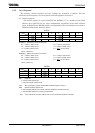
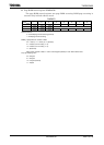
MAMR0
7 6 5 4 3 2 1 0
Bit symbol M0V20 M0V19 M0V18 M0V17 M0V16 M0V15 M0V14-9 M0V8
Read/Write R/W
After reset 1 1 1 1 1 1 1 1
M0V<20:8>
Enables or masks comparison of the addresses. M0V20
to M0V8 are corresponding to addresses A20 to A8.
The bit of M0V14
to M0V9 is corresponding to address A14 to A9 by 1 bit. If “0” is set, the comparison between
the value of the address bus and the start address is enabled. If “1” is set, the comparison is masked.
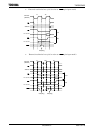
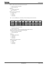
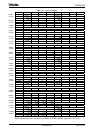
MAMR1
7 6 5 4 3 2 1 0
Bit symbol M1V21 M1V20 M1V19 M1V18 M1V17 M1V16 M1V15-9 M1V8
Read/Write R/W
After reset 1 1 1 1 1 1 1 1
M1V<21:8>
Enables or masks comparison of the addresses. M1V21 to M1V8 are corresponding to addresses A21 to A8.
The bits of M1V15 to M1V9 are corresponding to address A15 to A9 by 1 bit. If “0” is set, the comparison between
the value of the address bus and the start address is enabled. If “1” is set, the comparison is masked.
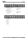
MAMRn (n = 2 to 3)
7 6 5 4 3 2 1 0
Bit symbol MnV22 MnV21 MnV20 MnV19 MnV18 MnV17 MnV16 MnV15
Read/Write R/W
After reset 1 1 1 1 1 1 1 1
MnV<22:15>
Enables or masks comparison of the addresses. MnV22 to MnV15 are corresponding to addresses A22 to A15.
If “0” is set, the comparison between the value of the address bus and the start address is enabled. If “1” is set,
the comparison is masked.
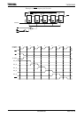
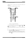
After a reset, MASR0 to MASR3 and MAMR0 to MAMR3 are set to “FFH”. B0CSH<B0E>, B1CSH<B1E>, and
B3CSH<B3E> are reset to “0”. This disables the CS0, CS1, and CS3 areas. However, B2CSH<B2M> is reset to
“0” and B2CSH<B2E> to “1”, and CS2 is enabled 000000H to FFFFFFH. Also the bus width and the number of
waits specified in BEXCSH/L are used for accessing address except the specified CS0 to CS3 area.