TMP92CM22
2007-02-16
92CM22-117
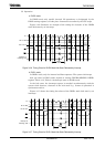
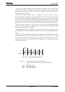
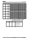
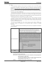
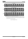
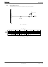
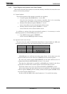
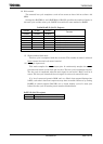
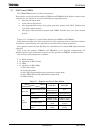
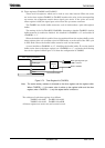
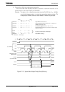
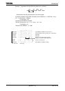
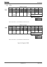
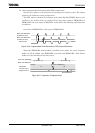
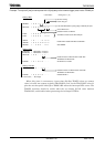
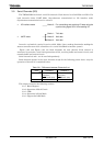
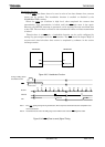
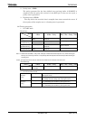
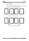
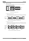
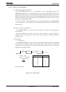
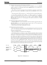
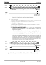
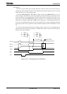
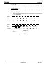
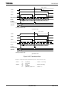
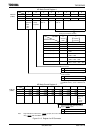
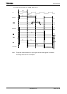
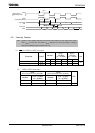
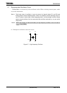
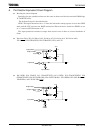
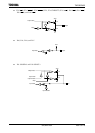
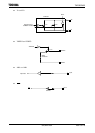
(4) 8-bit PWM (Pulse width modulation) output mode
This mode is only valid for TMRA0. In this mode, a PWM pulse with the maximum
resolution of 8 bits can be output.
When TMRA0 is used the PWM pulse is output on the TA1OUT pin (which is also
used as PC1). TMRA1 can also be used as an 8-bit timer.
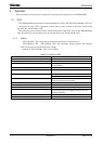
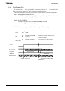
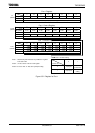
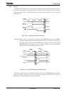
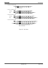
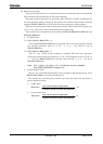
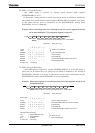
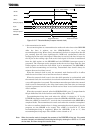
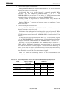
The timer output is inverted when the up counter (UC0) matches the value set in
the timer register TA0REG or when 2
n
counter overflow occurs (n = 6, 7, or 8 as
specified by TA01MOD<PWM01:00>). The up counter UC0 is cleared when 2
n
counter
overflow occurs.
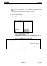
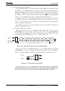
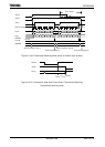
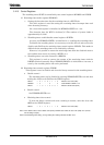
The following conditions must be satisfied before this PWM mode can be used.
Value set in TA0REG < Value of set for 2
n
counter overflow
Value set in TA0REG ≠ 0
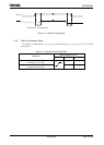
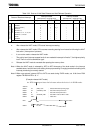
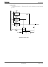
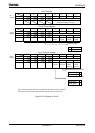
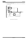
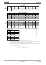
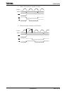
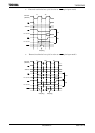
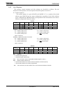
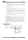
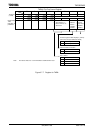
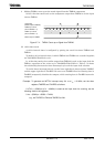
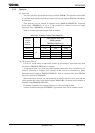
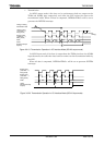
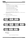
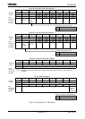
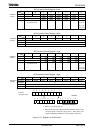
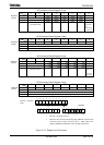
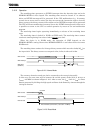
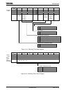
Figure 3.7.16 8-Bit Output Wave Form
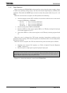
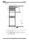
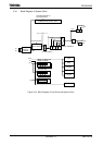
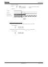
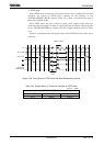
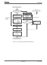
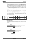
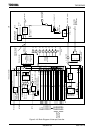
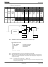
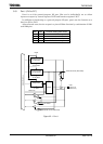
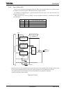
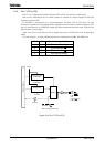
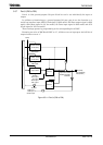
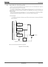
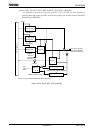
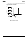
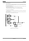
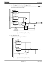
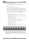
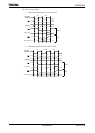
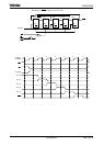
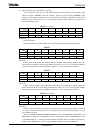
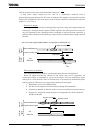
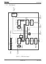
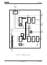
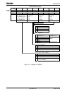
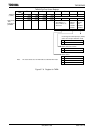
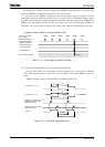
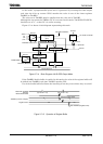
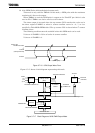
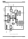
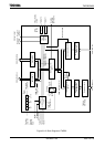
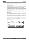
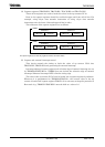
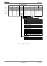
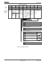
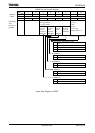
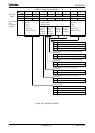
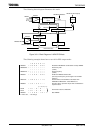
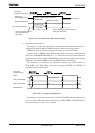
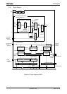
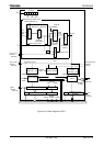
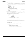
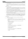
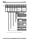
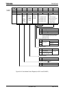
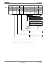
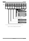
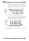
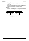
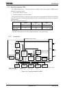
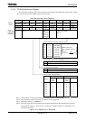
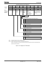
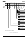
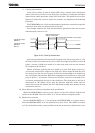
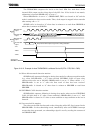
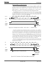
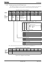
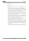
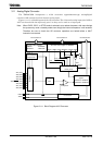
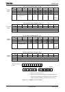
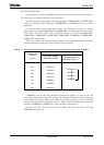
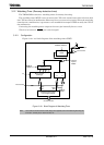
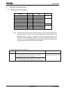
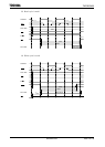
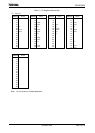
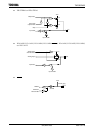
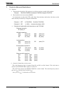
Figure 3.7.17 shows a block diagram representing this mode.
Figure 3.7.17 Block Diagram of 8-Bit PWM Output Mode
Match with
TA0REG and UC0
TA1OUT
t
PWM
(PWM cycle)
2
n
overflo
(Interrupt INTTA0)
Selector
8-bit up counter
(UC0)
Comparator
TA0IN
φT1
φT4
T16
TA01MOD<TA0CLK1:0>
TA1FF
TA0REG
Register buffer
Selector
TA01RUN<TA0RDE>
TA0REG-WR
TA01RUN<TA0RUN>
TA1OUT
TA1FFCR
<TA1FFIE>
Shift trigge
Internal data bus
Clear
2
n
overflow
control
INTTA0
TA01MOD
<PWM01:00>
Overflow
Inversion