


TMP92CM22
2007-02-16
92CM22-184
3.10.6 Data Transfer in I
2
C Bus Mode
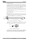
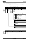
(1) Device initialization
In first, set the SBI0BR1<P4EN>, SBI0CR1<ACK, SCK2:0>. Set SBI0BR1<P4EN>
to “1” and clear bits 7 to 5 and 3 in the SBI0CR1 to “0”.
Next, set a slave address <SA6:0> and the <ALS> (<ALS> = “0” when an addressing
format) to the I2C0AR.
And, write “000” to SBI0CR2<MST, TRX, BB>, “1” to <PIN>, “10” to <SBIM1:0> and
“00” to <SWRST1:0>. Set initialization status to slave receiver mode by this setting.
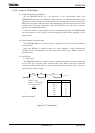
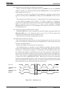
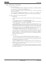
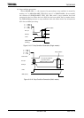
(2) Start condition and slave address generation
1. Master mode
In the master mode, the start condition and the slave address are generated as
follows.
In first, check a bus free status (when SBI0SR<BB> = “0”).
Set the SBI0CR1<ACK> to “1” (Acknowledge mode) and specify a slave address
and a direction bit to be transmitted to the SBI0DBR.
When SBI0SR<BB> = “0”, the start condition are generated by writing “1111” to
SBI0CR2<MST, TRX, BB, PIN>. Subsequently to the start condition, nine clocks
are output from the SCL pin. While eight clocks are output, the slave address and
the direction bit which are set to the SBI0DBR. At the 9th clock, the SDA line is
released and the acknowledge signal is received from the slave device.
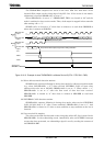
An INTSBE interrupt request generate at the falling edge of the 9th clock. The
<PIN> is cleared to “0”. In the master mode, the SCL pin is pulled down to the low
level while <PIN> is “0”. When an interrupt request is generated, the <TRX> is
changed according to the direction bit only when an acknowledge signal is
returned from the slave device.
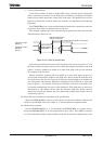
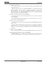
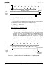
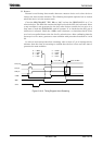
2. Slave mode
In the slave mode, the start condition and the slave address are received.
After the start condition is received from the master device, while eight clocks
are output from the SCL pin, the slave address and the direction bit that are
output from the master device are received.
When a GENERAL CALL or the same address as the slave address set in
I2C0AR is received, the SDA line is pulled down to the low level at the 9th clock,
and the acknowledge signal is output.
An INTSBE interrupt request is generated on the falling edge of the 9th clock.
The <PIN> is cleared to “0”. In slave mode the SCL line is pulled down to the low
level while the <PIN> = “0”.