


TMP92CM22
2007-02-16
92CM22-15
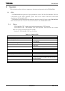
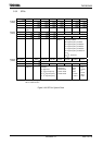
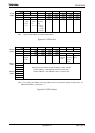
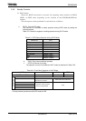
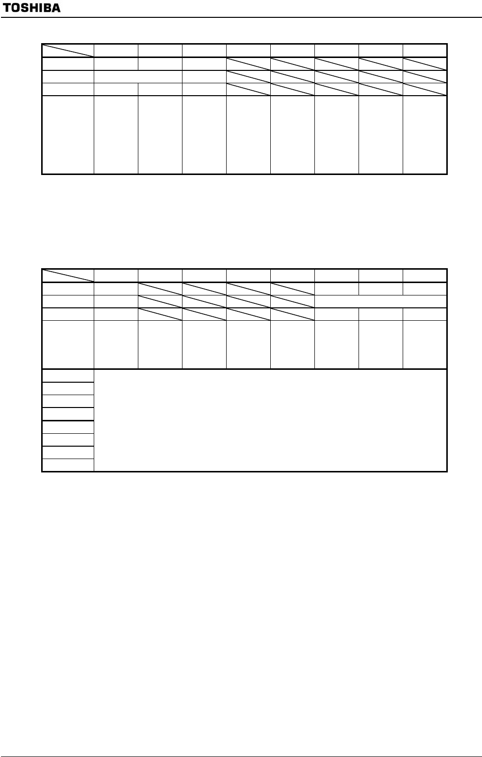
7 6 5 4 3 2 1 0
Bit symbol PLLON FCSEL LWUPFG
Read/Write R/W R
After reset 0 0 0
Function 0: PLL
stop
1: PLL
run
0: fc =
OSCH
1: fc =
PLL (× 4)
PLL
warm-up
flag
0: Don’t
end up
or stop
1: End up
Note: Logic of PLLCR<LWUPFG> is different DFM of 900/L1.
Figure 3.3.4 SFR for PLL
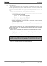
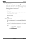
7 6 5 4 3 2 1 0
Bit symbol PROTECT EXTIN DRVOSCH −
Read/Write R R/W
After reset 0 0 1 1
Function Protect
0: OFF
1: ON
1: fc
external
clock
fc oscillator
driver ability
1: Normal
0: Weak
Always
write “1”.
Bit symbol
Read/Write
After reset
Function
Bit symbol
Read/Write
After reset
Function
Switching the protect ON/OFF by write to following 1st-KEY, 2nd-KEY
1st-KEY: EMCCR1 = 5AH, EMCCR2 = A5H in succession write
2nd-KEY: EMCCR1 = A5H, EMCCR2 = 5AH in succession write
Note: In case restarting the oscillator in the stop oscillation state (e.g. Restart the oscillator in STOP mode), set
EMCCR0<DRVOSCH>, <DRVOSCL>= “1”.
Figure 3.3.5 SFR for Noise
PLLCR
(10E8H)
EMCCR0
(10E3H)
EMCCR1
(10E4H)
EMCCR2
(10E5H)