


TMP92CM22
2007-02-16
92CM22-148
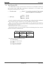
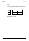
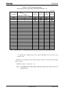
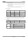
Table 3.9.3 UART Baud Rate Selection
(when using baud rate generater and BR0CR<BR0ADDE> = 0)
Unit (kbps)
f
SYS
[MHz]
Input Clock
Frequency Divider
φT0
(f
SYS
/4)
φT2
(f
SYS
/16)
φT8
(f
SYS
/64)
φT32
(f
SYS
/256)
9.8304 2 76.800 19.200 4.800 1.200
↑ 4 38.400 9.600 2.400 0.600
↑ 8 19.200 4.800 1.200 0.300
↑ 10 9.600 2.400 0.600 0.150
12.2880 5 38.400 9.600 2.400 0.600
↑ A 19.200 4.800 1.200 0.300
14.7456 2 115.200 28.800 7.200 1.800
↑ 3 76.800 19.200 4.800 1.200
↑ 6 38.400 9.600 2.400 0.600
↑ C 19.200 4.800 1.200 0.300
19.6608 1 307.200 76.800 19.200 4.800
↑ 2 153.600 38.400 9.600 2.400
↑ 4 76.800 19.200 4.800 1.200
↑ 8 38.400 9.600 2.400 0.600
↑ 10 19.200 4.800 1.200 0.300
22.1184 3 115.200 28.800 7.200 1.800
24.5760 1 384.000 96.000 24.000 6.000
↑ 2 192.000 48.000 12.000 3.000
↑ 4 96.000 24.000 6.000 1.500
↑ 5 76.800 19.200 4.800 1.200
↑ 8 48.000 12.000 3.000 0.750
↑ A 38.400 9.600 2.400 0.600
↑ 10 24.000 6.000 1.500 0.375
Note 1: Transfer rates in I/O interface mode are eight times faster than the values given above.
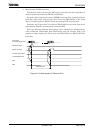
In UART mode, TMRA match detect signal (TA0TRG) can be used for serial
transfer clock.
Method for calculating the timer output frequency which is needed when outputting
trigger of timer
TA0TRG frequency = Baud rate × 16
Note: The TMRA0 match detect signal cannot be used as the transfer clock in I/O
Interface mode.