TMP92CM22
2007-02-16
92CM22-141
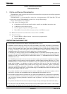
3.9 Serial Channels (SIO)
The TMP92CM22 includes 2 serial I/O channels. Each channel is called SIO0 and SIO1. For
both channels either UART Mode (Asynchronous transmission) or I/O interface mode
(Synchronous transmission) can be selected.
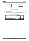
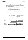
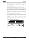
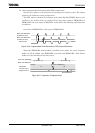
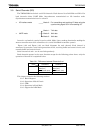
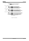
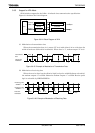
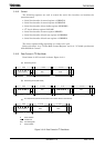
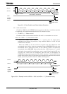
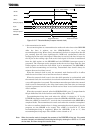
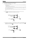
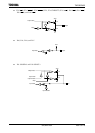
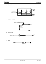
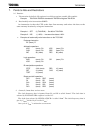
• I/O interface mode
Mode 0: For transmitting and receiving I/O data using the
synchronizing signal SCLK for extending I/O.
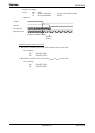
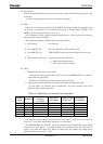
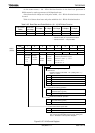
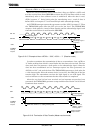
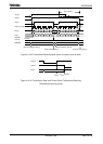
Mode 1: 7-bit data
• UART mode Mode 2: 8-bit data
Mode 3: 9-bit data
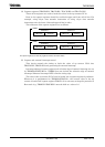
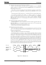
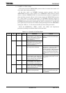
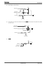
In mode 1 and mode 2 a parity bit can be added. Mode 3 has a wakeup function for making the
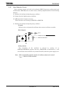
master controller start slave controllers via a serial link (Multi-controller system).
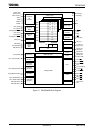
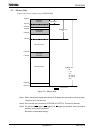
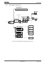
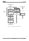
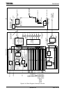
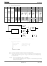
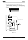
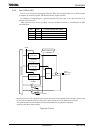
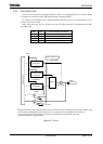
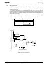
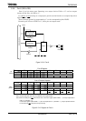
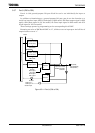
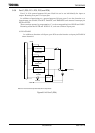
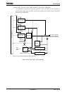
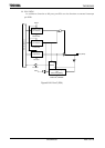
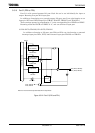
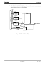
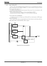
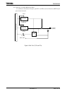
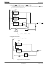
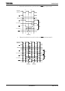
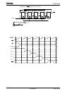
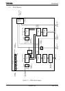
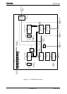
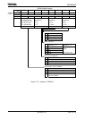
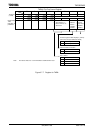
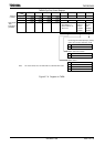
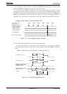
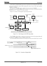
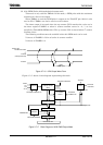
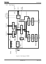
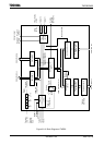
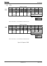
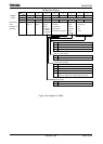
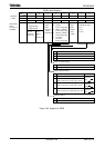
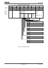
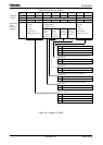
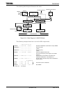
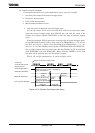
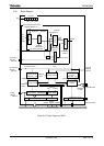
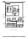
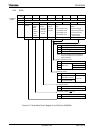
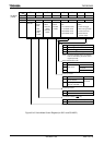
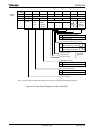
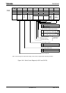
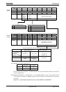
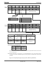
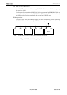
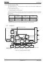
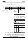
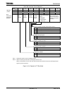
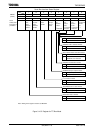
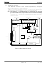
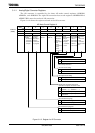
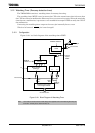
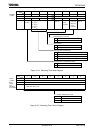
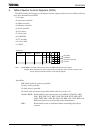
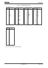
Figure 3.9.2 and Figure 3.9.3 are block diagrams for each channel. Each channel is
structured in prescaler, serial clock generation circuit, receiving buffer and control circuit, and
transfer buffer and control circuit.
Serial channels 0 and 1 can be used independently.
Both channels operate in the same function except for the following points; hence only the
operation of channel 0 is explained below.
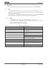
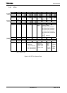
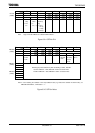
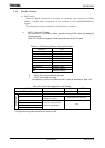
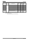
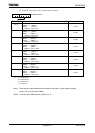
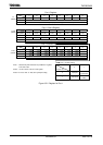
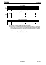
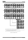
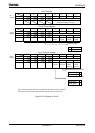
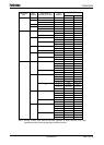
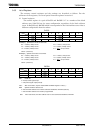
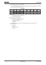
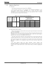
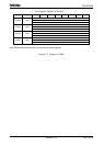
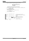
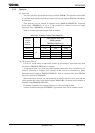
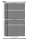
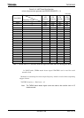
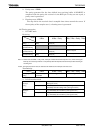
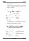
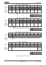
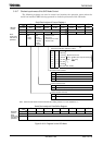
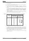
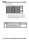
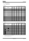
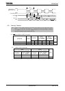
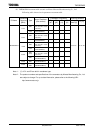
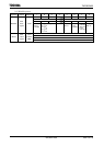
Table 3.9.1 Differences between Channels 0 to 1
Channel 0 Channel 1
Pin name TXD0 (PF0)
RXD0 (PF1)
CTS0 /SCLK0 (PF2)
TXD1 (PF3)
RXD1 (PF4)
CTS1/SCLK1 (PF5)
IrDA mode Yes No
This chapter contains the following sections:
3.9.1 Block Diagram
3.9.2 Operation of Each Circuit
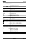
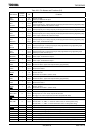
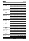
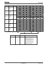
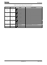
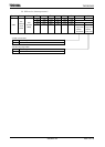
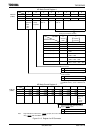
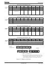
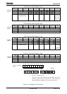
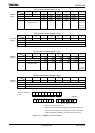
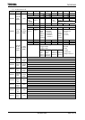
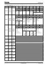
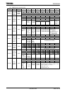
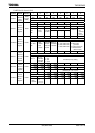
3.9.3 SFRs
3.9.4 Operation in Each Mode
3.9.5 Support for IrDA Mode