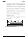
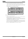
TMP92CM22
2007-02-16
92CM22-138
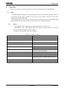
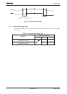
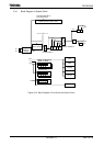
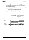
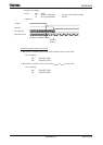
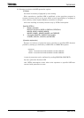
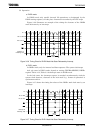
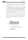
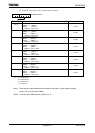
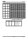
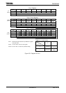
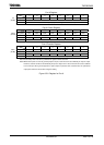
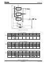
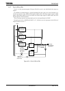
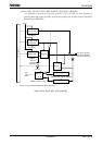
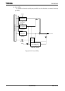
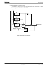
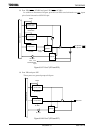
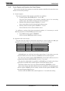
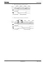
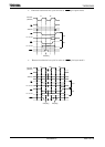
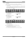
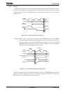
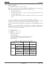
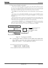
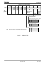
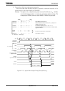
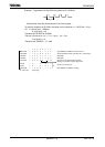
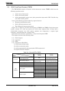
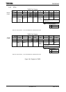
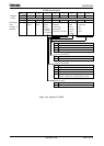
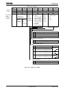
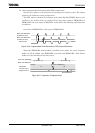
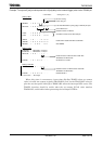
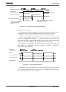
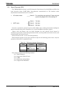
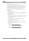
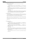
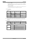
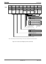
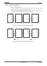
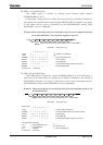
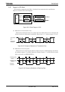
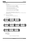
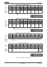
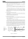
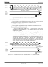
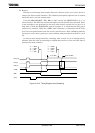
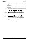
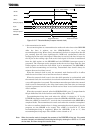
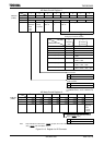
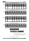
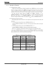
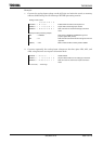
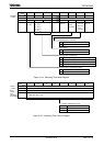
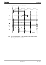
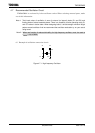
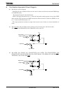
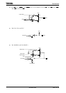
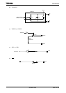
Figure 3.8.13 One-shot Pulse Output (without delay)
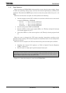
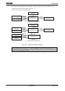
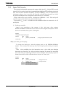
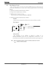
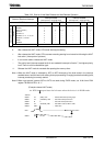
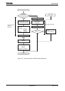
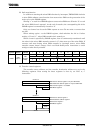
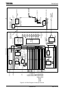
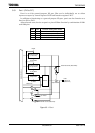
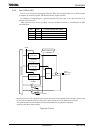
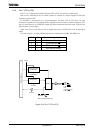
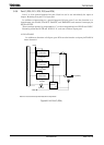
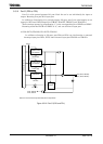
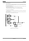
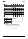
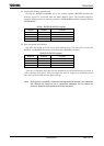
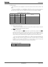
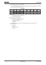
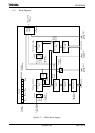
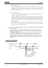
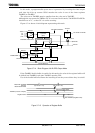
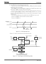
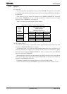
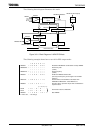
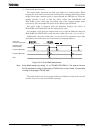
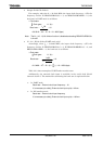
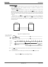
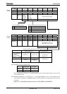
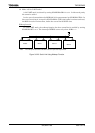
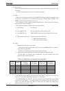
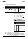
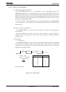
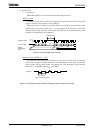
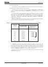
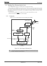
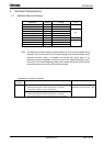
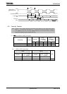
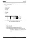
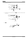
2. Frequency measurement
The frequency of the external clock can be measured in this mode. Frequency is
measured by the 8-bit timers TMRA23 and the 16-bit timer/event counter.
TMRA23 is used to setting of measurement time by inversion TA3FF.
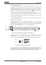
Counter clock in TMRB0 select TB1IN0 pin input, and count by external clock
input. Set to TB1MOD<TB1CPM1:0> = “11”. The value of the up counter (UC12) is
loaded into the capture register TB0CP0H/L at the rise edge of the timer flip-flop
TA1FF of 8-bit timers (TMRA1), and into TB0CP1H/L at its fall edge.
The frequency is calculated by difference between the loaded values in
TB1CP0H/L and TB1CP1H/L when the interrupt (INTTA2 or INTTA3) is
generates by either 8-bit timer.
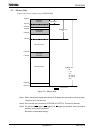
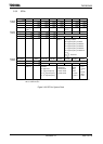
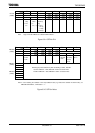
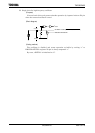
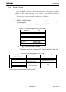
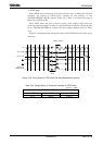
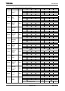
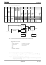
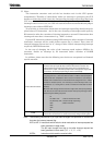
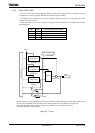
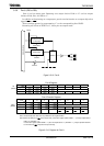
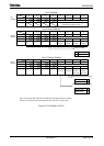
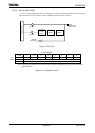
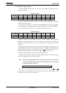
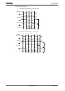
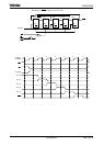
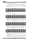
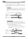
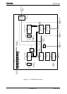
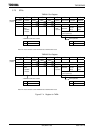
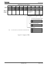
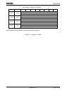
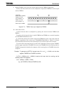
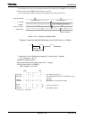
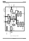
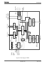
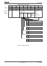
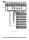
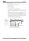
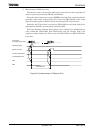
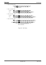
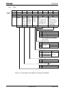
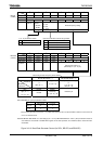
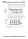
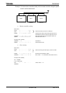
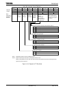
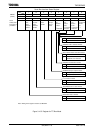
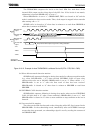
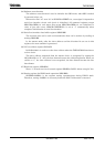
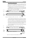
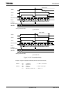
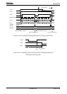
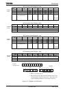
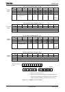
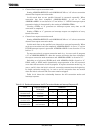
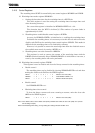
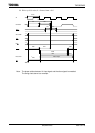
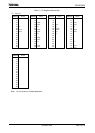
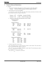
Figure 3.8.14 Frequency Measurement
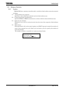
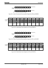
For example, if the value for the level 1 width of TA3FF of the 8-bit timer is set
to 0.5 s and the difference between the values in TB1CP0H/L and TB1CP1H/L is
100, the frequency is 100 ÷ 0.5 s = 200 Hz.
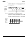
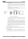
TB1IN0 input
(External trigger pulse)
c
Load into capture register TB1CP0H/L
generate INT4.
Match with TB1RG1H/L
Timer out
ut TB1OUT0
in
c
p
Pulse width
(p)
Inversion enable
Count clock
(Prescaler output clock)
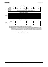
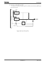
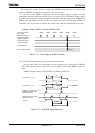
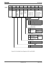
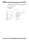
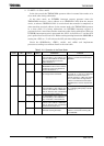
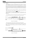
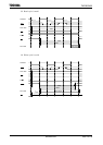
Generate INTTB11.
Load into capture register 1
TB1CP1H/L.
Set it to disable that inversion caused by
loading into TB1CP1H/L.
Set it to enable that inversion
caused by loading into
TB1CP0H/L.
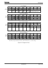
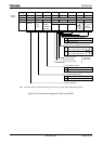
C1 C2
C1
C2 C2
C1
TA3FF
Load into TB1CP0H/L
Count clock
(TB1IN0 pin input )
Load into TB1CP1H/L
INTTA2/INTTA3