


TMP92CM22
2007-02-16
92CM22-199
3.11 Analog/Digital Converter
The TMP92CM22 incorporates a 10-bit successive approximation-type analog/digital
converter (AD converter) with 8-channel analog input.
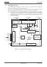
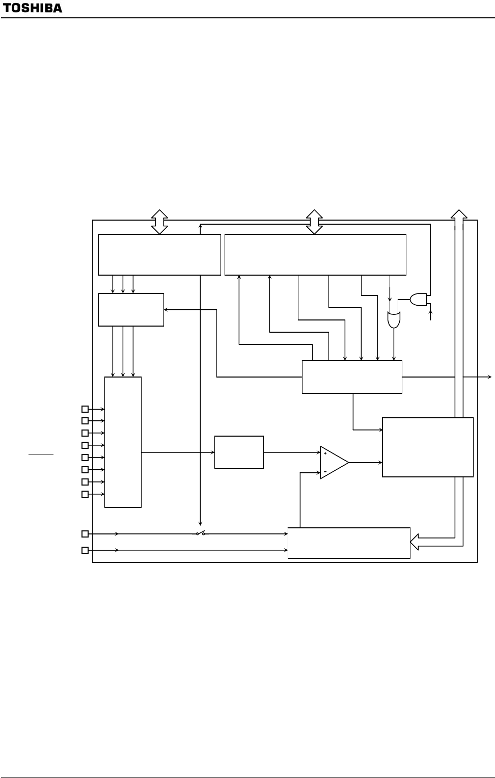
Figure 3.11.1 is a block diagram of the AD converter. The 8-channel analog input pins (AN0 to
AN7) are shared with the input-only port G so they can be used as an input port.
Note: When IDLE2, IDLE1, or STOP mode is selected, as to reduce the power, with some timings
the system may enter a standby mode even though the internal comparator is still enabled.
Therefore be sure to check that AD converter operations are halted before a HALT
instruction is executed.
Figure 3.11.1 Block Diagram of AD Converter
Internal data bus
AD mode control register 0 ADMOD0
<EOCF><ADBF><ITM0><REPEAT><SCAN><ADS>
AD mode control register 1
ADMOD1 <ADTRGE>
<ADCH2:0> <VREFON>
AD converter
control circuit
Scan
Repeat
Interrupt
Busy
End
Start
ADTRG
AD conversion result
register
ADREG0L to ADREG7L
ADREG0H to ADREG7H
DA converter
Sample
hold
Multiplexer
Channel selection
control circuit
Comparater
AN7 (PG7)
AN6 (PG6)
AN5 (PG5)
AN4 (PG4)
AN3/
ADTRG (PG3)
AN2 (PG2)
AN1 (PG1)
AN0 (PG0)
VREFH
VREFL
Interrupt
request
INTAD
Internal data bus Internal data bus