TMP92CM22
2007-02-16
92CM22-121
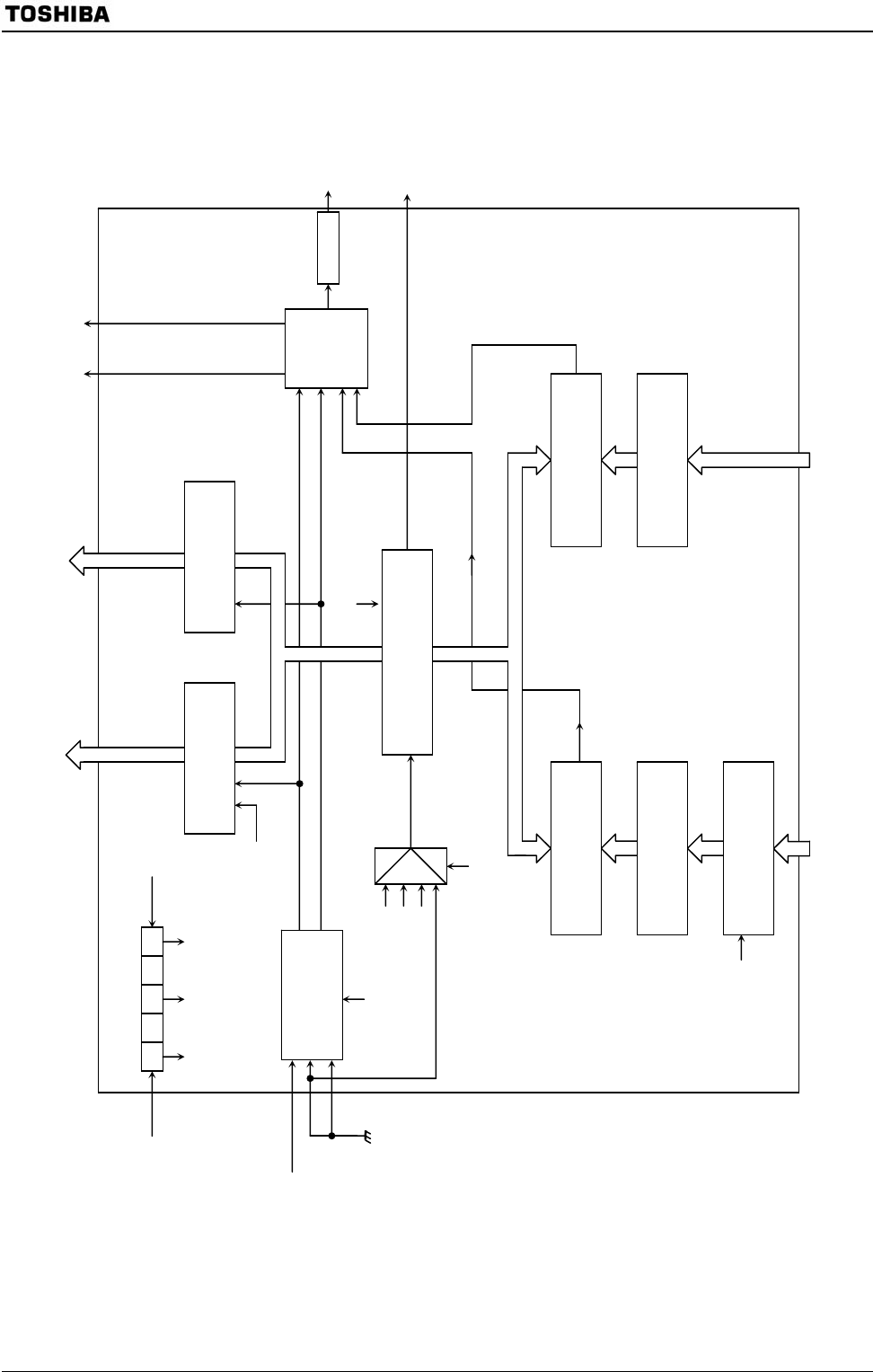
3.8.1 Block Diagram
Figure 3.8.1 Block Diagram of TMRB0
Capture,
external interrupt
control
Timer
flip-flop
control
Match detection
Match
detection
32 16 8 4 2
φT1 φT4 φT16
Run/
clear
φT1
φT4
φT16
TB0MOD<TB0CLK1:0>
Prescaler
clock: φT0
Selecto
r
Register buffer 10
TB0RUN<TB0RUN>
TB0MOD<TB0CLE>
TB0FF0
Internal data bus
TB0RUN
<TB0RDE>
TB0RUN
<TB0PRUN>
Intenal data bus
TB0MOD
<TB0CPM1:0>
Register 1
INTTB01
TB0OUT0
16-bit timer register
TB0REG0H/L
16-bit comparator
(CP10)
16-bit timer register
TB0RG1H/L
16-bit comparator (CP11)
TB0MOD
<TB0CP0I>
Internal data bus Internal data bus
Register 0
INTTB00
Timer flip-flop
output
Time
r
flip-flop
Overflow
interrupt
INTTBOF0
Capture register 0
TB0CP0H/L
Caputure register 1
TB0CP1H/L
TA1OUT
(from TMRA01)
16-bit up counter
(UC10)
Count
clock
Interrupt output


