


TMP92CM22
2007-02-16
92CM22-124
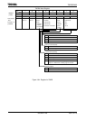
(3) Timer registers (TB0RG0H/L and TB0RG1H/L)
These two 16-bit registers are used to set the interval time. When the value in the up
counter UC10 matches the value set in this timer register, the comparator match
detect signal will go active.
Setting data for both upper and lower timer registers TB0RG0H/L and TB0RG1H/L
is always needed. For example, either using 2-byte data transfer instruction or using
1-byte data transfer instruction twice for lower 8 bits and upper 8 bits in order.
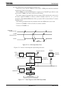
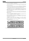
The TB0RG0H/L timer register has a double-buffer structure, which is paired with
register buffer 10. The value set in TB0RUN<TB0RDE> determines whether the
double-buffer structure is enabled or disabled: It is disabled when <TB0RDE> = 0, and
enabled when <TB0RDE> = 1.
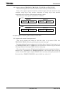
When the double buffer is enabled, data is transferred from the register buffer to the
timer register when the values in the up counter (UC10) and the timer register
TB0RG1H/L match.
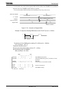
After a reset, TB0RG0H/L and TB0RG1H/L are undefined. If the 16-bit timer is to be
used after a reset, data should be written to it beforehand.
On a reset <TB0RDE> is initialized to 0, disabling the double buffer. To use the
double buffer, write data to the timer register, set <TB0RDE> to 1, then write data to
the register buffer as shown below.
TB0RG0H/L and the register buffer both have the same memory addresses
(001188H and 001189H) allocated to them. If <TB0RDE> = 0, the value is written to
both the timer register and the register buffer. If <TB0RDE> = 1, the value is written
to the register buffer only.
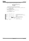
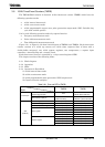
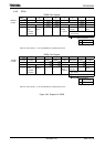
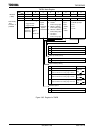
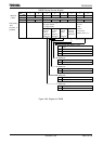
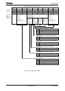
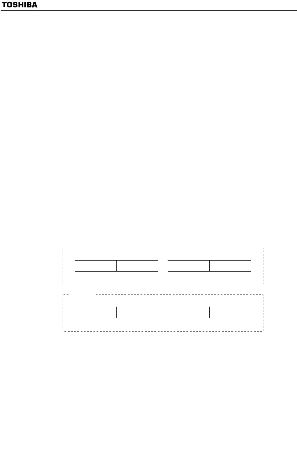
The addresses of the timer registers are as follows:
The timer registers are write-only registers and thus cannot be read.
TMRB0
1189H 1188H 118BH 118AH
TB0RG0H/L TB0RG1H/L
Upper 8 bits
(TB0RG0H)
Lower 8 bits
(TB0RG0L)
TMRB1
1199H 1198H 119BH 119AH
TB1RG0H/L TB1RG1H/L
Upper 8 bits
(TB0RG1H)
Lower 8 bits
(TB0RG1L)
Upper 8 bits
(TB1RG0H)
Lowe
r
8 bits
(TB1RG0L)
Upper 8 bits
(TB1RG1H)
Lower 8 bits
(TB1RG1L)