TMP92CM22
2007-02-16
92CM22-84
(4) Wait control
The external bus cycle completes a wait of two states at least (100 ns at f
SYS
= 20
MHz).
Setting the <BnWW2:0> and <BnWR2:0> of BnCSL specifies the number of waits in
the read cycle and the write cycle. BnWW is set with the same method as BnWR.
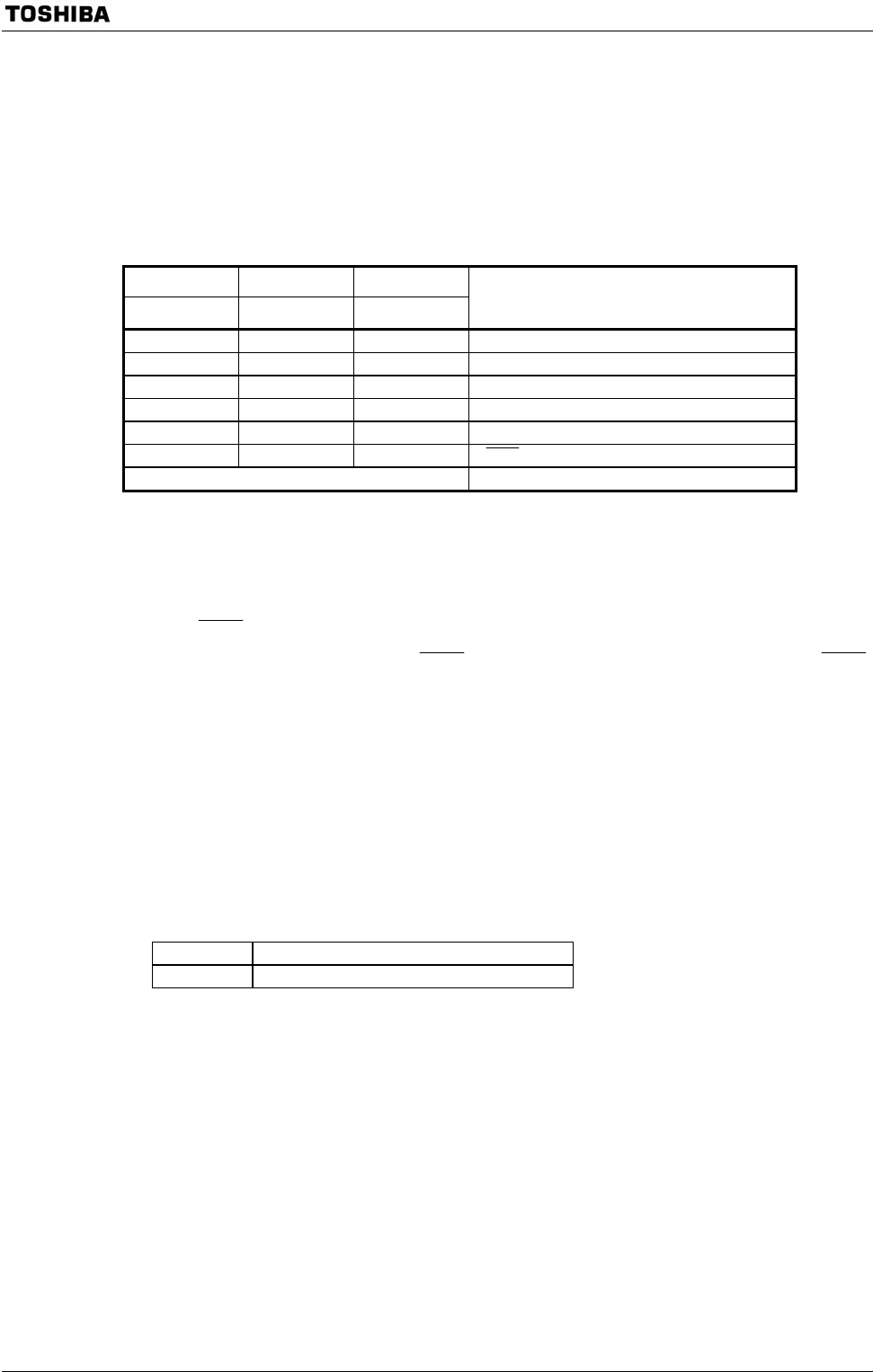
BnWW/BnWR Bit (BnCSL Register)
BnWW2 BnWR1 BnWW0
BnWR2 BnWW1 BnWR0
Function
0 0 1 2 states (0 waits) access fixed mode
0 1 0 3 states (1 wait) access fixed mode (Default)
1 0 1 4 states (2 waits) access fixed mode
1 1 0 5 states (3 waits) access fixed mode
1 1 1 6 states (4 waits) access fixed mode
0 1 1 WAIT pin input mode
Others (Reserved)
(i) Waits number fixed mode
The bus cycle is completed with the set states. The number of states is selected
from 2 states (0 waits) to 6 states (4 waits).
(ii)
WAIT pin input mode
This mode samples the
WAIT input pins. It continuously samples the WAIT
pin state and inserts a wait if the pin is active. The bus cycle is minimum 2 states.
The bus cycle is completed when the wait signal is non-active (“High” level) at 2
states. The bus cycle extends if the wait signal is active at 2 states and more.
If a lot of connected pertain ROM and etc. (Much data-output-floating-time
(tDF)), each other’s data-bus-output-recovery-time is trouble. However, by setting
BnREC of control register (BnCSH), can to insert dummy cycle of 1-state just
before first bus cycle of starting access another block address.
BnREC Bit (BnCSH register)
0 No dummy cycle is inserted (Default).
1 Dummy cycle is inserted.


