


TMP92CM22
2007-02-16
92CM22-200
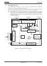
3.11.1 Analog/Digital Converter Registers
The AD converter is controlled by the three AD mode control registers: ADMOD0,
ADMOD1, and ADMOD2. The eight AD conversion data result registers (ADREG0H/L to
ADREG7H/L) store the results of AD conversion.
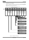
Figure 3.11.2 shows the registers related to the AD converter.
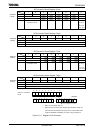
AD Mode Control Register 0
7 6 5 4 3 2 1 0
Bit symbol EOCF ADBF − − ITM0 REPEAT SCAN ADS ADMOD0
(12B8H)
Read/Write R R/W
After reset 0 0 0 0 0 0 0 0
Function
AD
conversion
end flag
0: Conversion
in progress
1: Conversion
complete
AD
conversion
busy flag
0: Conversion
stopped
1: Conversion
in progress
Always
write “0”.
Always
write “0”.
Interrupt
specification
in
conversion
channel
fixed repeat
mode
0: Every
conversion
1: Every
fourth
conversion
Repeat
mode
specification
0: Single
conversion
1: Repeat
conversion
mode
Scan mode
specification
0: Conversion
channel
fixed mode
1: Conversion
channel
scan mode
AD
conversion
start
0: Don’t care
1: Start
conversion
Always 0 when
read.
0 Don’t care
1 Start AD conversion.
0 AD conversion channel fixed mode
1 AD conversion channel scan mode
0 AD single conversion mode
1 AD repeat conversion mode
Channel fixed repeat conversion mode
<SCAN> = “0”, <REPEAT> = “1”
0 Generates interrupt every conversion.
1 Generates interrupt every fourth
conversion.
0 AD conversion stopped
1 AD conversion in progress
0 Before or during AD conversion
1 AD conversion complete
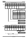
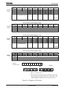
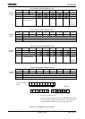
Figure 3.11.2 Register for AD Converter
AD conversion start
AD scan mode setting
AD repeat mode setting
Specify AD conversion interrupt for
channel fixed repeat conversion mode
AD conversion busy flag
Note: Always read as 0.
AD conversion in progress