


TMP92CM22
2007-02-16
92CM22-14
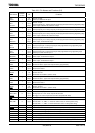
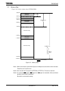
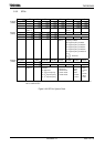
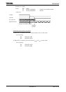
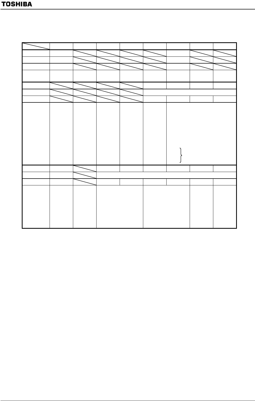
3.3.2 SFRs
7 6 5 4 3 2 1 0
Bit symbol − −
Read/Write R/W R/W
After reset 1 0
Function Always
write “1”.
Always
write “0”.
Bit symbol − GEAR2 GEAR1 GEAR0
Read/Write R/W
After reset 0 1 0 0
Function Always
write “0”.
Select gear value of high-
frequency oscillator
000: High-frequency oscillator
001: High-frequency oscillator/2
010: High-frequency oscillator/4
011: High-frequency oscillator/8
100: High-frequency oscillator/16
101:
110: Reserved
111:
Bit symbol − WUPTM1 WUPTM0 HALTM1 HALTM0 SELDRV DRVE
Read/Write R/W R/W
After reset 0 1 0 1 1 0 0
Function Always
write “0”.
Select WUP time for
oscillator
00: Reserved
01: 2
8
/Input frequency
10: 2
14
/Input frequency
11: 2
16
/Input frequency
Select HALT mode
00: Reserved
01: STOP mode
10: IDLE1 mode
11: IDLE2 mode
<DRVE>
Select
using
mode
0: STOP
1: IDLE1
1: Pin
state
control
in
STOP/
IDLE1
mode
Note: The unassigned register, SYSCR0<bit6:3>, SYSCR0<bit1:0>, SYSCR1<bit7:4>, and SYSCR2<bit6> are
RD as undefined value.
Figure 3.3.3 SFR for System Clock
SYSCR0
(10E0H)
SYSCR1
(10E1H)
SYSCR2
(10E2H)