


TMP92CM22
2007-02-16
92CM22-177
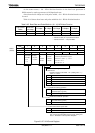
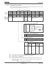
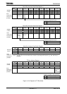
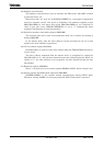
Serial Bus Interface Baud Rate Register 0
7 6 5 4 3 2 1 0
Bit symbol − I2SBI0 SBI0BR0
(1244H)
Read/Write W R/W
After reset 0 0
Function Always
write “0”.
IDLE2
0: Stop
1: Run
0 Stop
1 Run
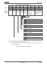
Serial Bus Interface Baud Rate Register 1
7 6 5 4 3 2 1 0
Bit symbol P4EN − SBI0BR1
(1245H)
Read/Write W
After reset 0 0
Function
Internal
clock
0: Stop
1: Run
Always
write “0”.
0 Stop
1 Run
Sirial Bus Interface Data Buffer Register
7 6 5 4 3 2 1 0
Bit symbol DB7 DB6 DB5 DB4 DB3 DB2 DB1 DB0 SBI0DBR
(1241H)
Read/Write R (Receiving)/W (Transmission)
After reset Undefined
Read-
modify-write
instruction is
prohibited.
Note 1: When writing transmission data, start from the MSB (Bit7). Receiving data is placed from LSB (Bit0).
Note 2: SBI0DBR can’t be read the written data. Therefore read-modify-write instruction (e.g., “BIT” instruction) is
prohibited.
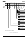
I
2
C Bus Address Register
7 6 5 4 3 2 1 0
Bit symbol SA6 SA5 SA4 SA3 SA2 SA1 SA0 ALS I2C0AR
(1242H)
Read/Write W
After reset 0 0 0 0 0 0 0 0
Read-
modify-write
instruction is
prohibited.
Function Slave address selection for when device is operating as slave device Address
recognition
mode
specification
0 Slave address recognition
1 Non slave address recognition
Figure 3.10.6 Register for I
2
C Bus Mode
Operation during IDLE 2 mode
Operation during IDLE 2 mode
Address recognition mode specification
Read-
modify-write
instruction is
prohibited.
Read-
modify-write
instruction is
prohibited.