


TMP92CM22
2007-02-16
92CM22-17
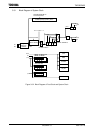
3.3.4 Clock Doubler (PLL)
PLL outputs the f
PLL
clock signal, which is four times as fast as f
OSCH
. A reset initializes
PLL to stop status, setting to PLLCR register is needed before use.
Like an oscillator, this circuit requires time to stabilize. This is called the lockup time.
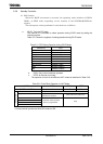
Note 1: Input frequency limitation for PLL
The limitation of input frequency (High-frequency oscillation) for PLL is the following.
f
OSCH
= 4 to 10 MHz (Vcc = 3.0 V to 3.6 V)
Note 2: PLLCR<LWUPFG>
The logic of PLLCR<LUPFG> is different from 900/L1’s DFM.
Be careful to judge an end of lockup time.
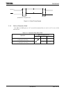
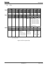
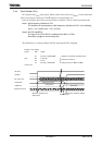
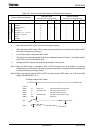
The following is a setting example for PLL starting and PLL stopping.
Example 1: PLL starting
PLLCR EQU 10E8H
LD (PLLCR), 10XXXXXXXB ; Enables PLL operation and starts lockup.
LUP: BIT 5, (PLLCR) ;
JR Z, LUP ;
Detects end of lockup.
LD (PLLCR), 11XXXXXXB ; Changes fc from 10 MHz to 40 MHz.
X: Don’t care
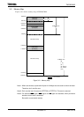
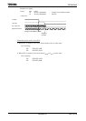
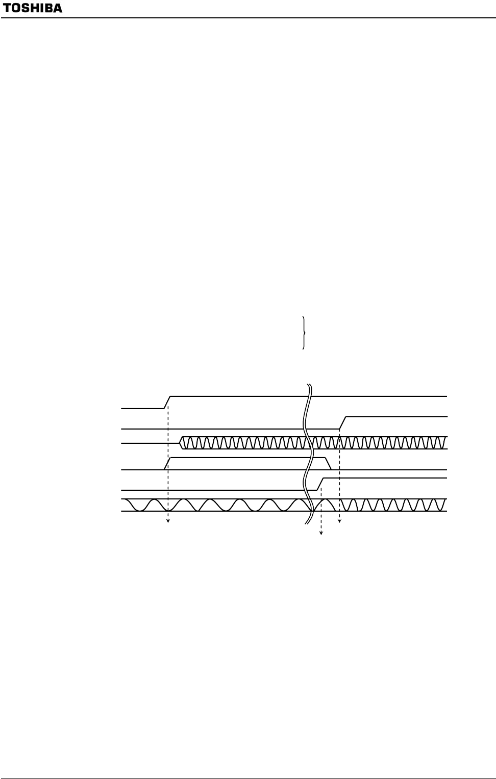
Count-up by f
OSCH
Changes from 10 MHz to 40 MHz.
Starts PLL operation and
starts lockup.
<PLLON>
<FCSEL>
PLL output: f
PLL
Lockup timer
<LWUPFG>
System clock f
SYS
After lockup
During lockup
Ends of lockup