


TMP92CM22
2007-02-16
92CM22-173
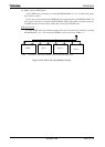
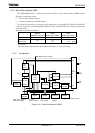
3.10.2 Control
The following registers are used to control the serial bus interface and monitor the
operation status.
• Serial bus interface 0 control register 1 (SBI0CR1)
• Serial bus interface 0 control register 2 (SBI0CR2)
• Serial bus interface 0 data buffer register (SBI0DBR)
• I
2
C bus 0 address register (I2C0AR)
• Serial bus interface 0 status register (SBI0SR)
• Serial bus interface 0 baud rate register 0 (SBI0BR0)
• Serial bus interface 0 baud rate register 1 (SBI0BR1)
The above registers differ depending on a mode to be used.
Refer to Section 3.10.4 “I
2
C Bus Mode Control Register” and 3.10.7 “Clocked-synchronous
8-Bit SIO Mode Control”.
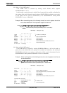
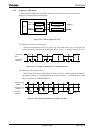
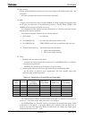
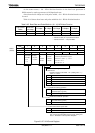
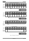
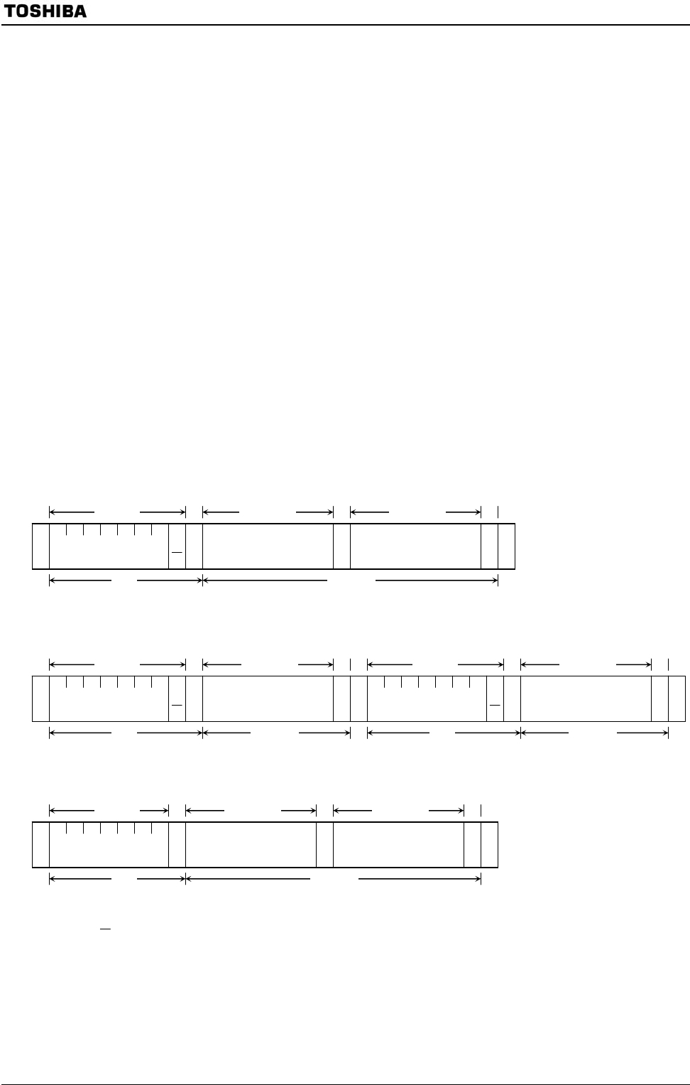
3.10.3 Data Format in I
2
C Bus Mode
Data format in I
2
C bus mode is shown Figure 3.10.3.
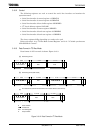
(a)
Addressing format
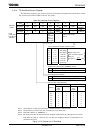
(b)
Addressing format (with restart)
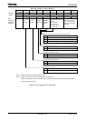
(c)
Free data format (transfer format transfer from master device to slave device)
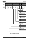
S: Start condition
R/
W : Direction bit
ACK: Acknowledge bit
P: Stop condition
Figure 3.10.2 Data Format in I
2
C Bus Mode
S Slave address Data
A
C
K
A
C
K
S Slave address Data
A
C
K
A
C
K
P
8 bits 1 1 to 8 bits 1 8bits 1 1 to 8 bits 1
1 1 or more 1 1 or more
R
/
W
R
/
W
8 bits
S Slave address
A
C
K
A
C
K
A
C
K
P
1 1 to 8 bits 1 1 to 8 bits 1
1 1 or more
R
/
W
Data Data
1
1
S Slave address Data
A
C
K
A
C
K
Data
A
C
K
P
8 bits
1
1 to 8 bits 1 to 8 bits
1 1 or more
A
C
K