


TMP92CM22
2007-02-16
92CM22-111
3.7.4 Operation in Each Mode
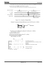
(1) 8-bit timer mode
Both TMRA0 and TMRA1 can be used independently as 8-bit interval timers.
When set function and count data, TMRA0 and TMRA1 should be stopped.
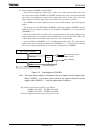
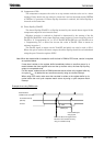
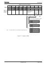
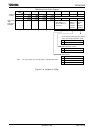
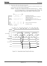
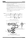
1. Generating interrupts at a fixed interval (using TMRA1)
To generate interrupts at constant intervals using TMRA1 (INTTA1), first stop
TMRA1 then set the operation mode, input clock and a cycle to TA01MOD and
TA1REG register, respectively. Then, enable the interrupt INTTA1 and start TMRA1
counting.
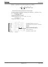
Example: To generate an INTTA1 interrupt every 40 μs at f
C
= 40 MHz, set each register
as follows:
MSB LSB
7 6 5 4 3210
TA01RUN ←
− X X X −
−
0 −
Stop TMRA1 and clear it to 0.
TA01MOD ← 0 0 X X 0 1 − − Select 8-bit timer mode and select φT1 (=(16/fc)s at f
C
=
40MHz) as the input clock.
TA1REG ← 0 1 1 0 0100 Set 40 μs ÷ φT1 = 100 = 64H to TAREG.
INTETA01 ← X 1 0 1 −
−
−
−
Enable INTTA1 and set it to Level 5.
TA01RUN ←
− X X X −
11− Start TMRA1 counting.
X : Don’t care, − : No change
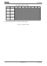
Select the input clock refers to
Table 3.7.3.
Table 3.7.3 Selecting Interrupt Interval and the Input Clock Using 8-Bit Timer
Input clock Interrupt Interval (at f
SYS
= 20 MHz) Resolution
φT1 (8/f
SYS
)
φT4 (32/f
SYS
)
φT16 (128/f
SYS
)
φT256 (2048/f
SYS
)
0.4 μs to 102.4 μs
1.6 μs to 409.6 μs
6.4 μs to 1.638 ms
102.4 μs to 26.21 ms
0.4 μs
1.6 μs
6.4 μs
102.4 μs
Note: The input clocks for TMRA0 and TMRA1 differ as follows:
TMRA0: Uses TMRA0 input (TA0IN) and can be selected from φT1, φT4, or φT16.
TMRA1: Matches output of TMRA0 (TA0TRG) and can be selected from φT1, φT16,
φT256.