


TMP92CM22
2007-02-16
92CM22-209
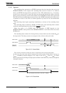
(5) AD conversion time
84 states (8.4 μs at f
SYS
= 20 MHz) are required for the AD conversion of one channel.
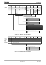
(6) Storing and reading the results of AD conversion
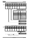
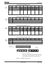
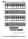
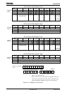
The AD conversion data upper and lower registers (ADREG0H/L to ADREG7H/L)
store the results of AD conversion. (ADREG0H/L to ADREG7H/L are read-only
registers.)
In channel fixed repeat conversion mode, the conversion results are stored
successively in registers ADREG0H/L to ADREG3H/L. In other modes the AN0, AN1,
AN2, AN3, AN4 AN5, AN6, AN7 conversion results are stored in ADREG0H/L,
ADREG1H/L, ADREG2H/L, ADREG3H/L, ADREG4H/L, ADREG5H/L, ADREG6H/L,
ADREG7H/L respectively.
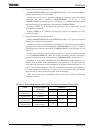
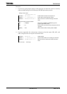
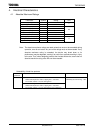
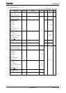
Table 3.11.3 shows the correspondence between the analog input channels and the
registers which are used to hold the results of AD conversion.
Table 3.11.3 Correspondence between Analog Input Channel and AD Conversion Result Register
AD Conversion Result Register
Analog Input
Channel
(Port G)
Conversion Modes
Other than at Right
Channel Fixed Repeat
Conversion Mode
(ADMOD0<ITM0>= “1”)
AN0 ADREG0H/L
AN1 ADREG1H/L
AN2 ADREG2H/L
ADREG0H/L
AN3 ADREG3H/L
ADREG1H/L
AN4 ADREG4H/L
ADREG2H/L
AN5 ADREG5H/L
ADREG3H/L
AN6 ADREG6H/L
AN7 ADREG7H/L
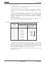
<ADRxRF>, bit0 of the AD conversion data lower register, is used as the AD
conversion data storage flag. The storage flag indicates whether the AD conversion
result register has been read or not. When a conversion result is stored in the AD
conversion result register, the flag is set to “1”. When either of the AD conversion result
registers (ADREGxH or ADREGxL) is read, the flag is cleared to “0”.
Reading the AD conversion result also clears the AD conversion end flag
ADMOD0<EOCF> to “0”.