


TMP92CM22
2007-02-16
92CM22-113
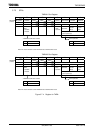
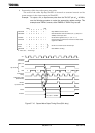
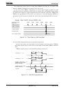
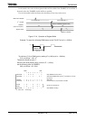
3. Making TMRA1 count up on the match signal from the TMRA0 comparator
Select 8-bit timer mode and set the comparator output from TMRA0 to be the input
clock to TMRA1.
Figure 3.7.11 TMRA1 Count up on Signal from TMRA0
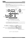
(2) 16-bit timer mode
A 16-bit interval timer is configured by pairing the two 8-bit timers TMRA0 and
TMRA1.
To make a 16-bit interval timer, in which TMRA0 and TMRA1 are cascaded together,
set TA01MOD<TA01M1:0> to 01.
In 16-bit timer mode, the overflow output from TMRA0 is used as the input clock for
TMRA1, regardless of the value set in TA01MOD<TA01CLK1:0>.
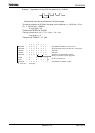
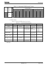
Table 3.7.3 shows
the relationship between the timer (Interrupt) cycle and the input clock selection.
To set the timer interrupt interval, set the lower eight bits in timer register TA0REG
and the upper eight bits in TA1REG. Be sure to set TA0REG first (As entering data in
TA0REG temporarily disables the compare, while entering data in TA1REG starts the
compare).
Example: To generate an INTTA1 interrupt every 0.4 s at f
C
= 40 MHz, set the timer
registers TA0REG and TA1REG as follows:
If φT16 (= (256/fc)s at f
C
= 40MHz) is used as the input clock for counting, set the
following value in the registers:
0.4 s ÷ (256/fc)s = 62500 = F424H;
e.g., set TA1REG to F4H and TA0REG to 24H.
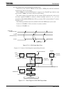
2 34512345 12 31
1 2 1
Comparator
(Match output forTMRA0)
TMRA0 up counter
(
when TA0REG = 5
)
TMRA1 up counter
(
when TA1REG = 2
)
Match output for TMRA1