


TMP92CM22
2007-02-16
92CM22-112
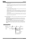
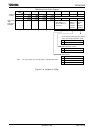
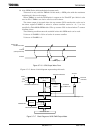
2. Generating a 50% duty ratio square wave pulse
The state of the timer flip-flop (TA1FF1) is inverted at constant intervals and its
status output via the timer output pin (TA1OUT).
Example: To output a 2.4 μs square wave pulse from the TA1OUT pin at f
C
= 40 MHz,
use the following procedure to make the appropriate register settings. This
example uses TMRA1; however, either TMRA0 or TMRA1 may be used.
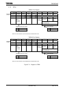
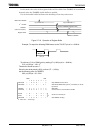
MSB LSB
7 6 5 4 3210
TA01RUN ←
− X X X −
−
0 −
Stop TMRA1 and clear it to 0.
TA01MOD ← 0 0 X X 0 1 −
−
Select 8-bit timer mode and select φT1 (=(16/fc)s at f
C
=
40MHz) as the input clock.
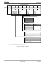
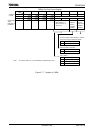
TA1REG ← 0 0 0 0 0011 Set the timer register to 2.4 μs ÷ φT1 ÷ 2 = 3.
TA1FFCR ← X X X X 1011 Clear TA1FF to 0 and set it to invert on the match detect
signal from TMRA1.
PCCR ←
X − − X −
X1−
PCFC ←
X − − X −
X1−
Set PC1 to function as the TA1OUT pin.
TA01RUN ←
− X X X −
11−
Start TMRA1 counting.
X : Don’t care, − : No change
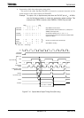
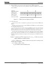
Figure 3.7.10 Square Wave Output Timing Chart (50% duty)
1.2
μ
s at f
C
=
40 MHz
0 1 2 3 0 1 2 3 0 1 2 3 0
φT1
TA01RUN
<TA1RUN>
Bit7 to 2
Bit1
Bit0
INTTA1
TA1FF
TA1OUT
Up counter
Comparato
r
timing
Comparator output
(Match detect)
Up counter clea
r