


TMP92CM22
2007-02-16
92CM22-80
3.6.3 Basic Functions and Register Setting
In this section, setting of the block address area, the connecting memory and the
number of waits out of the memory controller’s functions are described.
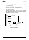
(1) Block address area specification
The block address area is specified by two registers.
The memory start address register (MSAR) sets the start address of the block
address areas. The memory controller compares between the register value and the
address every bus cycles. The address bit which is masked by the memory address
mask register (MAMR) is not compared by the memory controller. The block address
area size is determined by setting the memory address mask register. The set value in
the register is compared with the block address area on the bus. If the compared result
is a match, the memory controller sets the chip select signal (
CS ) to “low”.
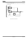
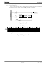
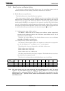
(i) Setting memory start address register
The MS23 to MS16 bits of the memory start address register respectively
correspond with addresses A23 to A16. The lower start address A15 to A0 are
always set to address 0000H.
Therefore the start address of the block address area are set to addresses
000000H to FF0000H every 64 Kbytes.
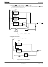
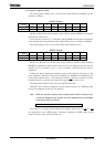
(ii) Setting memory address mask registers
The memory address mask register sets whether an address bit is compared or
not. Set the register to “0” to compare, or to “1” not to compare.
The address bit to be set is depended on the block address area.
Block address area 0: A20 to A8
Block address area 1: A21 to A8
Block address area 2 to 3: A22 to A15
The above-mentioned bits are always compared. The block address area size is
determined by the compared result.
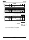
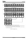
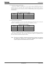
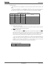
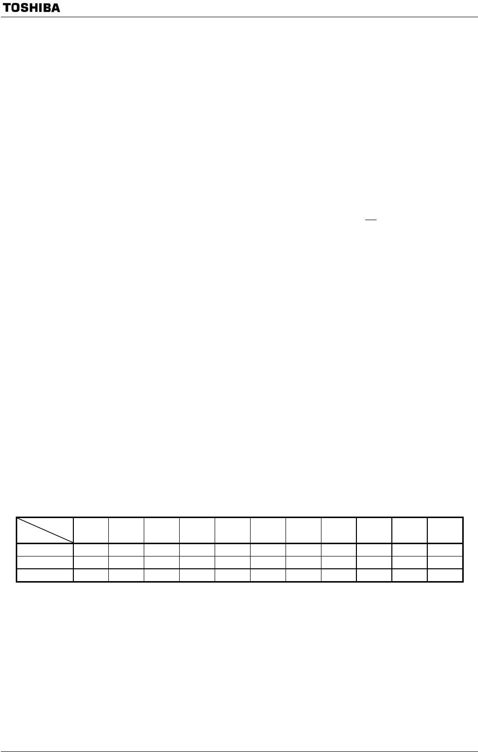
The size to be set depending on the block address area is as follows.
Size (bytes)
CS area
256 512 32 K 64 K 128 K 256 K 512 K 1 M 2 M 4 M 8 M
CS0 ○ ○ ○ ○ ○ ○ ○ ○ ○
CS1 ○ ○ ○ ○ ○ ○ ○ ○ ○
CS2 to CS3 ○ ○ ○ ○ ○ ○ ○ ○ ○
Note: After reset release, only the control register of the block address area 2 is valid. The control
register of the block address area 2 has <B2M> bit. Setting <B2M> bit to “0” sets the block
address area 2 to addresses 000000H to FFFFFFH. State of after reset release is set this.
Setting <B2M> bit to “1” specifies the start address and the address area size as it is in the other
block address area.