


TMP92CM22
2007-02-16
92CM22-31
3.4.1 General-purpose Interrupt Processing
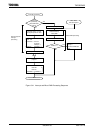
When the CPU accepts an interrupt, it usually performs the following sequence of
operations. That is also the same as TLCS-900/L, TLCS-900/H, and TLCS-900/L1.
(1) The CPU reads the interrupt vector from the interrupt controller.
If the same level interrupts occur simultaneously, the interrupt controller generates an
interrupt vector in accordance with the default priority and clears the interrupt
request.
(The default priority is already fixed for each interrupt: The smaller vector value has
the higher priority level.)
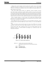
(2) The CPU pushes the value of program counter (PC) and status register (SR) onto the
stack area (indicated by XSP).
(3) The CPU sets the value which is the priority level of the accepted interrupt plus 1 (+1)
to the interrupt mask register <IFF2:0>. However, if the priority level of the accepted
interrupt is 7, the register’s value is set to 7.
(4) The CPU increases the interrupt nesting counter INTNEST by 1 (+1).
(5) The CPU jumps to the address indicated by the data at address “FFFF00H + Interrupt
vector” and starts the interrupt processing routine.
When the CPU completed the interrupt processing, use the RETI instruction to return to
the main routine. RETI restores the contents of program counter (PC) and status register
(SR) from the stack and decreases the interrupt nesting counter INTNEST by 1(−1).
Non-maskable interrupts cannot be disabled by a user program. Maskable interrupts,
however, can be enabled or disabled by a user program. A program can set the priority level
for each interrupt source. (A priority level setting of 0 or 7 will disable an interrupt
request.)
If an interrupt request which has a priority level equal to or greater than the value of the
CPU interrupt mask register <IFF2:0> comes out, the CPU accepts its interrupt. Then, the
CPU interrupt mask register <IFF2:0> is set to the value of the priority level for the
accepted interrupt plus 1(+1).
Therefore, if an interrupt is generated with a higher level than the current interrupt
during it’s processing, the CPU accepts the later interrupt and goes to the nesting status of
interrupt processing.
Moreover, if the CPU receives another interrupt request while performing the said (1) to
(5) processing steps of the current interrupt, the latest interrupt request is sampled
immediately after execution of the first instruction of the current interrupt processing
routine. Specifying DI as the start instruction disables maskable interrupt nesting.
A reset initializes the interrupt mask register <IFF2:0> to “7”, disabling all maskable
interrupts.
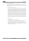
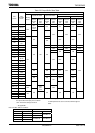
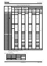
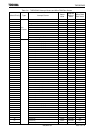
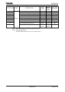
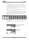
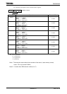
Table 3.4.1 shows the TMP92CM22 interrupt vectors and micro DMA start vectors. The
address FFFF00H to FFFFFFH (256 bytes) is assigned for the interrupt vector area.