


TMP92CM22
2007-02-16
92CM22-196
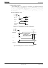
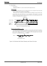
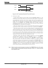
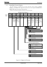
Figure 3.10.26 Transmission Data Hold Time at End Transmit
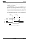
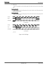
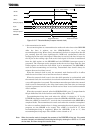
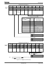
2. 8-bit receive mode
Set the control register to receive mode and set the SBI0CR1<SIOS> to “1” for
switching to receive mode. Data is received into the shift register via the SI pin
and synchronized with the serial clock, starting from the least significant bit
(LSB). When the 8-bit data is received, the data is transferred from the shift
register to the SBI0DBR. The INTSBE0 (Buffer full) interrupt request is
generated to request that the received data be read. The data is then read from
the SBI0DBR by the interrupt service program.
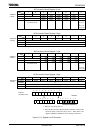
When the internal clock is used, the serial clock will stop and the automatic
wait function will be in effect until the received data is read from the SBI0DBR.
When the external clock is used, since shift operation is synchronized with an
external clock pulse, the received data should be read from the SBI0DBR before
the next serial clock pulse is input. If the received data is not read, further data to
be received is canceled. The maximum transfer speed when an external clock is
used is determined by the delay time between the time when an interrupt request
is generated and the time when the received data is read.
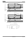
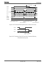
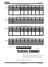
Receiving of data ends when the <SIOS> is cleared to “0” by the INTSBE0
interrupt service program or when the <SIOINH> is set to “1”. If <SIOS> is
cleared to “0”, received data is transferred to the SBI0DBR in complete blocks.
The received mode ends when the transfer is completed. In order to confirm
whether data is being received properly by the program, the SBI0SR<SIOF> to be
sensed. The <SIOF> is cleared to “0” when receiving is completed. When it is
confirmed that receiving has been completed, the last data is read. When the
<SIOINH> is set to “1”, data receiving stops. The <SIOF> is cleared to “0” (The
received data becomes invalid, therefore no need to read it).
Note: When the transfer mode is changed, the contents of the SBI0DBR will be lost. If the mode
must be changed, conclude data receiving by clearing the <SIOS> to “0”, read the last data,
then change the mode.
SCK pin
Bit7 Bit6
<SIOF>
SO pin
t
SODH
= 3.5/f
SYS
[s] (Min)