


TMP92CM22
2007-02-16
92CM22-182
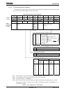
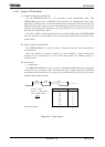
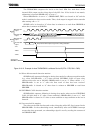
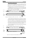
The TMP92CM22 compares the levels on the bus’s SDA line with those of the
internal SDA output on the rising edge of the SCL line. If the levels do not match,
arbitration is lost and SBI0SR<AL> is set to “1”.
When SBI0SR<AL> is set to “1”, SBI0SR<MST, TRX> are cleared to “00” and the
mode is switched to slave receiver mode. Thus, clock output is stopped in data transfer
after setting <AL> = “1”.
SBI0SR <AL> is cleared to “0” when data is written to or read from SBI0DBR or
when data is written to SBI0CR2.
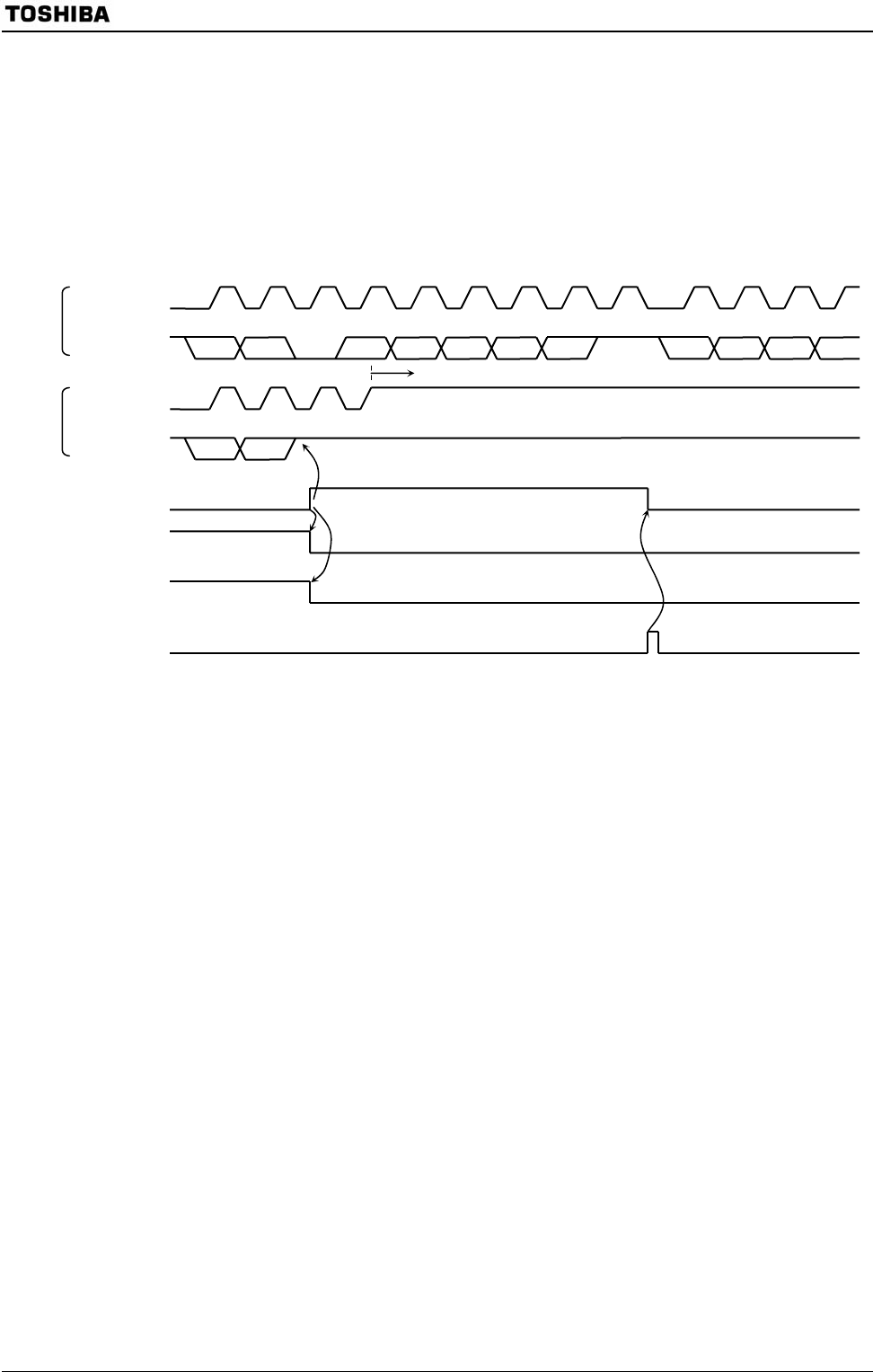
Figure 3.10.12 Example of when TMP92CM22 is a Master Device B (D7A = D7B, D6A = D6B)
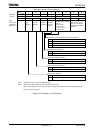
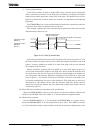
(11) Slave address match detection monitor
SBI0SR<AAS> operates following in during slave mode; In address recognition mode
(e.g., when I2C0AR<ALS> = “0”), when received GENERAL CALL or same slave
address with value set to I2C0AR, SBI0SR<AAS> is set to “1”. When <ALS> = “1”,
SBI0SR<AAS> is set to “1” after the first word of data has been received.
SBI0SR<AAS> is cleared to “0” when data is written to SBI0DBR or read from
SBI0DBR.
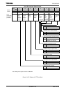
(12) GENERAL CALL detection monitor
SBI0SR<AD0> operates following in during slave mode; when received GENERAL
CALL (all 8-bit data is “0”, after a start condition), SBI0SR<AD0> is set to “1”. And
SBI0SR<AD0> is cleared to “0” when a start condition or stop condition on the bus is
detected.
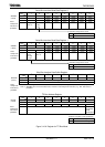
(13) Last received bit monitor
The value on the SDA line detected on the rising edge of the SCL line is stored in the
SBI0SR<LRB>. In the acknowledge mode, immediately after an INTSBE0 interrupt
request has been generated, an acknowledge signal is read by reading the contents of
the SBI0SR<LRB>.
1
D7A D6A D4A D3A D2A D1A D0A
Internal SCL
output
<AL>
A
ccessed to
SBI0DBR or SBI0CR2
2 3 4 657981 2 34
D7A’ D6A’
D5A’
D4A’
1
2 3 4
D7B D6B
Keep internal SDA output to high level as losing arbitration
Stop the clock pulse
Internal SDA
output
Internal SCL
output
Internal SDA
output
<MST>
<TRX>
Master
A
Master
B
D5A