TMP92CM22
2007-02-16
92CM22-203
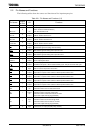
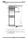
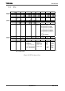
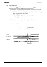
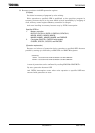
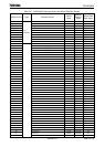
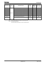
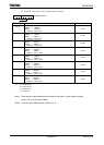
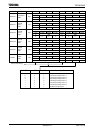
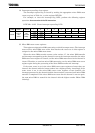
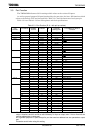
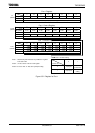
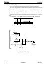
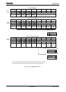
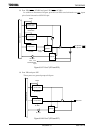
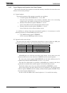
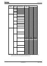
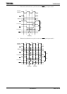
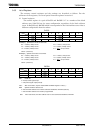
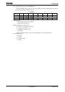
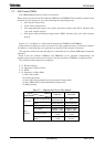
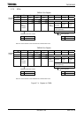
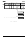
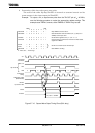
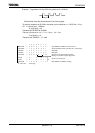
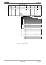
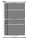
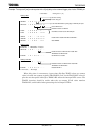
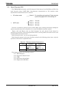
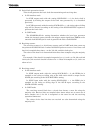
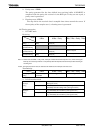
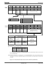
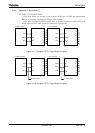
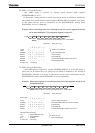
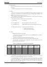
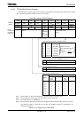
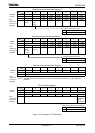
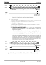
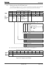
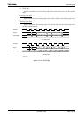
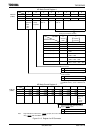
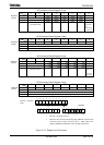
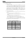
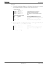
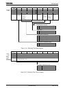
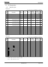
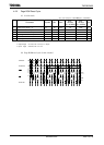
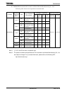
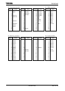
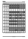
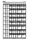
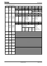
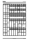
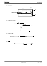
AD Conversion Result Register 2 Low
7 6 5 4 3 2 1 0
Bit symbol ADR21 ADR20 ADR2RFADREG2L
(12A4H)
Read/Write R R
After reset Undefined 0
Function Stores lower 2 bits of AD
conversion result.
AD conversion
data storage
flag
1: Conversion
result stored
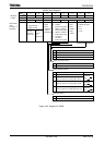
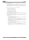
AD Conversion Result Register 2 High
7 6 5 4 3 2 1 0
Bit symbol ADR29 ADR28 ADR27 ADR26 ADR25 ADR24 ADR23 ADR22 ADREG2H
(12A5H)
Read/Write R
After reset Undefined
Function Stores upper 8 bits of AD conversion result.
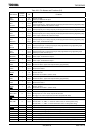
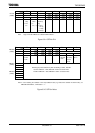
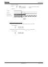
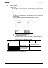
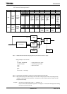
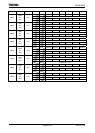
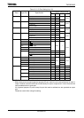
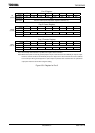
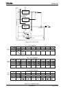
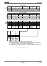
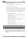
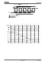
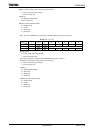
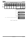
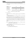
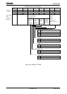
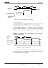
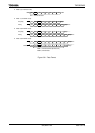
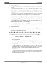
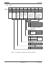
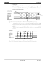
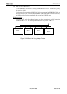
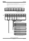
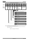
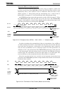
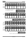
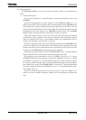
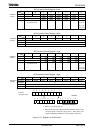
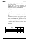
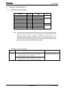
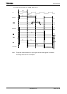
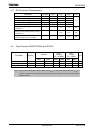
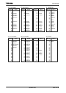
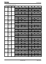
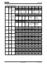
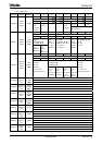
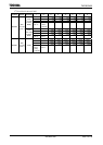
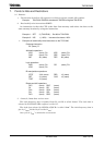
AD Conversion Result Register 3 Low
7 6 5 4 3 2 1 0
Bit symbol ADR31 ADR30 ADR3RFADREG3L
(12A6H)
Read/Write R R
After reset Undefined 0
Function Stores lower 2 bits of AD
conversion result.
AD conversion
data storage
flag
1: Conversion
result stored
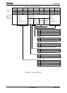
AD Conversion Result Register 3 High
7 6 5 4 3 2 1 0
Bit symbol ADR39 ADR38 ADR37 ADR36 ADR35 ADR34 ADR33 ADR32 ADREG3H
(12A7H)
Read/Write R
After reset Undefined
Function Stores upper 8 bits of AD conversion result.
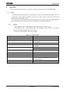
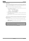
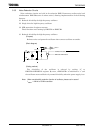
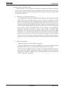
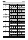
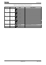
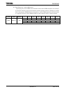
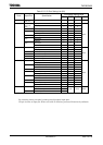
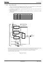
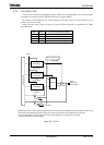
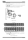
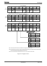
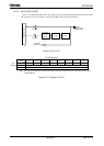
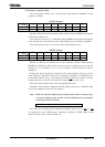
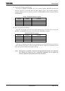
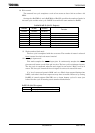
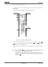
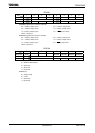
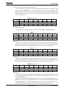
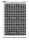
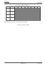
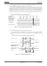
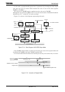
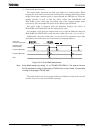
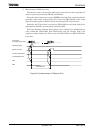
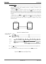
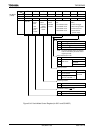
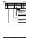
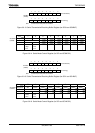
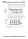
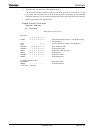
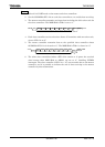
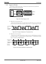
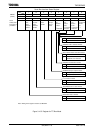
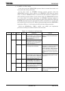
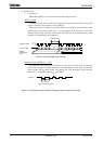
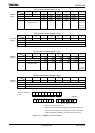
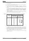
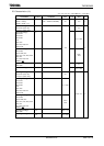
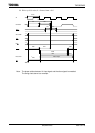
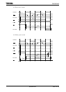
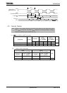
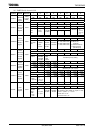
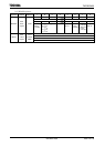
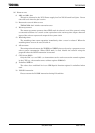
9 8 76543210
7 6 543210 76543 2 1 0
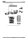
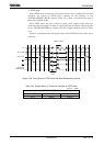
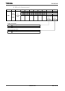
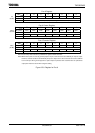
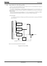
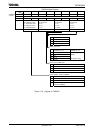
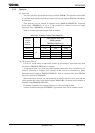
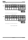
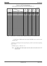
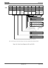
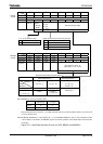
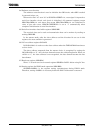
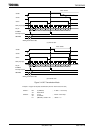
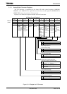
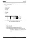
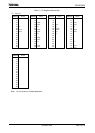
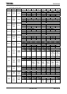
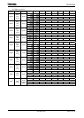
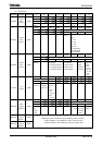
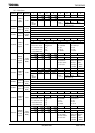
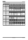
Figure 3.11.5 Register for AD Converter
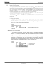
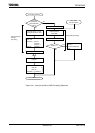
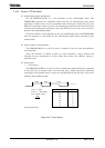
Channel × conversion
result
DREGxL
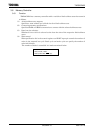
• Bits 5 to 1 are always read as 1.
• Bit0 is the AD conversion data storage flag <ADRxRF>. When the AD
conversion result is stored, the flag is set to 1. When either of the
registers (ADREGxH, ADREGxL) is read, the flag is cleared to 0.
DREGxH