


TMP92CM22
2007-02-16
92CM22-204
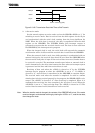
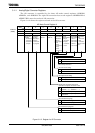
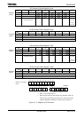
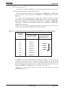
AD Conversion Result Register 4 Low
7 6 5 4 3 2 1 0
Bit symbol ADR41 ADR40 ADR4RFADREG4L
(12A8H)
Read/Write R R
After reset Undefined 0
Function Stores lower 2 bits of AD
conversion result.
AD conversion
data storage
flag
1: Conversion
result stored
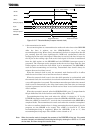
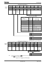
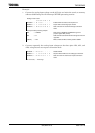
AD Conversion Result Register 4 High
7 6 5 4 3 2 1 0
Bit symbol ADR49 ADR48 ADR47 ADR46 ADR45 ADR44 ADR43 ADR42 ADREG4H
(12A9H)
Read/Write R
After reset Undefined
Function Stores upper 8 bits of AD conversion result.
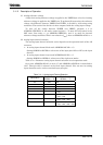
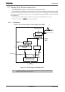
AD Conversion Result Register 5 Low
7 6 5 4 3 2 1 0
Bit symbol ADR51 ADR50 ADR5RFADREG5L
(12AAH)
Read/Write R R
After reset Undefined 0
Function Stores lower 2 bits of AD
conversion result.
AD conversion
data storage
flag
1: Conversion
result stored
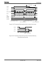
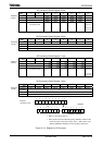
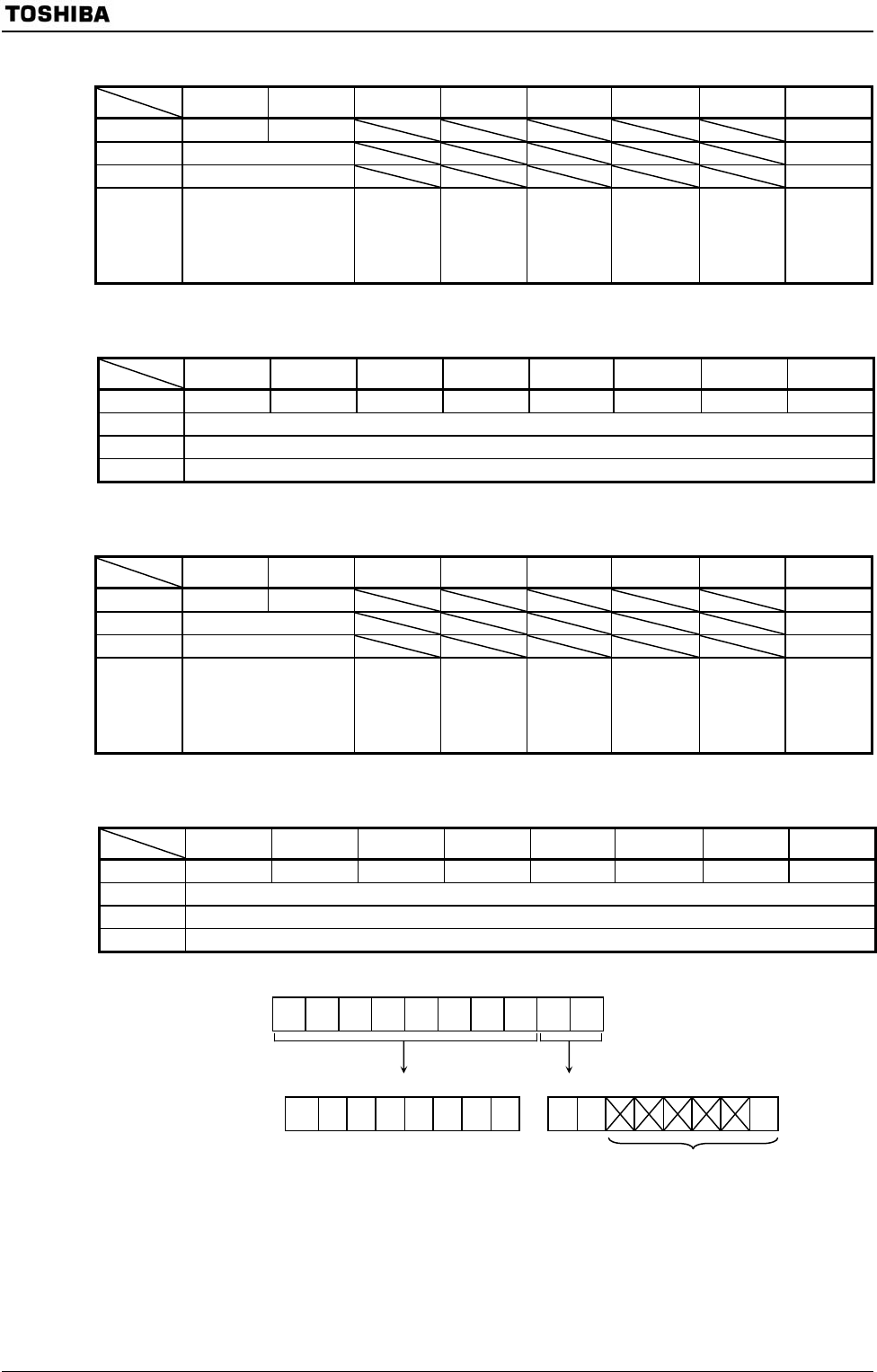
AD Conversion Result Register 5 High
7 6 5 4 3 2 1 0
Bit symbol ADR59 ADR58 ADR57 ADR56 ADR55 ADR54 ADR53 ADR52 ADREG5H
(12ABH)
Read/Write R
After reset Undefined
Function Stores upper 8 bits of AD conversion result.
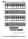
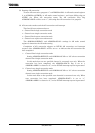
9 8 76543210
7 6 543210 76543 2 1 0
Figure 3.11.6 Register for AD Converter
Channel × conversion
result
A
DREGxL
• Bits 5 to 1 are always read as 1.
• Bit0 is the AD conversion data storage flag <ADRxRF>. When the AD
conversion result is stored, the flag is set to 1. When either of the
registers (ADREGxH, ADREGxL) is read, the flag is cleared to 0.
A
DREGxH