


TMP92CM22
2007-02-16
92CM22-159
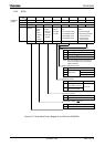
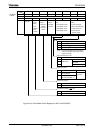
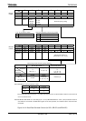
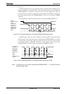
7 6 5 4 3 2 1 0
Bit symbol − BR1ADDE BR1CK1 BR1CK0 BR1S3 BR1S2 BR1S1 BR1S0BR1CR
(120BH)
Read/Write R/W
After reset 0 0 0 0 0 0 0 0
Function Always
write “0”.
+ (16 − K)/16
division
0: Disable
1: Enable
00: φT0
01: φT2
10: φT8
11: φT32
Divided frequency setting
7 6 5 4 3 2 1 0
Bit symbol BR1K3 BR1K2 BR1K1 BR1K0BR1ADD
(120CH)
Read/Write R/W
After reset 0 0 0 0
Function
Set frequency divisor “K”
(Divided by N + (16 − K)/16).
Baud rate generator frequency divisor setting
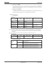
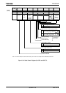
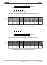
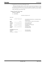
BR1CR<BR1ADDE> = 1 BR1CR<BR1ADDE> = 0
BR1CR
<BR1S3:0>
BR1ADD
<BR1K3:0>
0000 (N = 16)
or
0001 (N = 1)
0010 (N = 2)
1111 (N = 15)
0001 (N = 1) (UART only)
to
1111 (N = 15)
0000 (N = 16)
0000 Disable Disable
0001 (K = 1)
1111 (K = 15)
Disable
Divided by
N + (16 − K) / 16
Divided by N
Note1:Availability of +(16-K)/16 division function
N UART mode I/O mode
2 to 15 ○ ×
1 , 16 × ×
The baud rate generator can be set to “1” in UART mode only when the +(16-K)/16 division function is not used. Do not
use in I/O interface mode.
Note2:Set BR1CR <BR1ADDE> to 1 after setting K (K = 1 to 15) to BR1ADD<BR1K3:0> when +(16-K)/16 division function is
used. Writes to unused bits in the BR1ADD register do not affect operation, and undefined data is read from these
unused bits.
Figure 3.9.12 Baud Rate Generater Control (for SIO1, BR1CR, and BR1ADD)
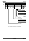
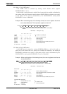
Input clock selection for baud rate generator
00 Internal clock φT0
01 Internal clock φT2
10 Internal clock φT8
11 Internal clock φT32
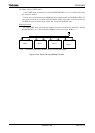
+ (16 − K)/16 divisions enable
0 Disabled
1 Enabled
~
~