


TMP92CM22
2007-02-16
92CM22-179
2. Clock synchronization
In the I
2
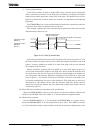
C bus mode, in order to wired-AND a bus, a master device which pulls
down a clock line to low level, in the first place, invalidate a clock pulse of another
master device which generates a high-level clock pulse. The master device with a
high-level clock pulse needs to detect the situation and implement the following
procedure.
The TMP92CM22 has a clock synchronization function for normal data transfer
even when more than one master exists on the bus.
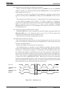
The example explains the clock synchronization procedures when two masters
simultaneously exist on a bus.
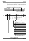
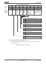
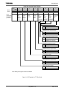
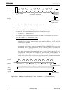
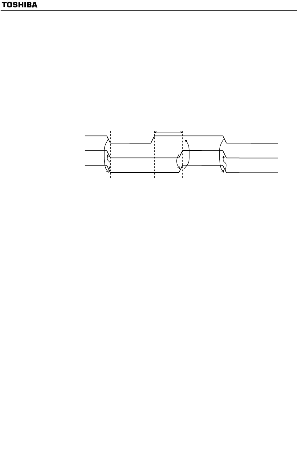
Figure 3.10.8 Clock Synchronization
As master A pulls down the internal SCL output to the low level at point “a”, the
SCL line of the bus becomes the low level. After detecting this situation, master B
resets a counter of high-level width of an own clock pulse and sets the internal
SCL output to the low level.
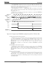
Master A finishes counting low-level width of an own clock pulse at point “b”
and sets the internal SCL output to the high level. Since master B holds the SCL
line of the bus at the low level, master A waits for counting high-level width of an
own clock pulse. After master B finishes counting low-level width of an own clock
pulse at point “c” and master A detects the SCL line of the bus at the high level,
and starts counting high level of an own clock pulse. The clock pulse on the bus is
determined by the master device with the shortest high-level width and the
master device with the longest low-level width from among those master devices
connected to the bus.
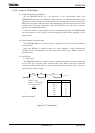
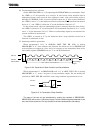
(4) Slave address and address recognition mode specification
When the TMP92CM22 is used as a slave device, set the slave address <SA6:0> and
<ALS> to the I2C0AR. Clear the <ALS> to “0” for the address recognition mode.
(5) Master/slave selection
Set the SBI0CR2<MST> to “1” for operating the TMP92CM22 as a master device.
Clear the SBI0CR2<MST> to “0” for operation as a slave device. The <MST> is cleared
to “0” by the hardware after a stop condition on the bus is detected or arbitration is lost.
Start couting high-level width of a clock pulse
Internal SCL output
(Master A)
Internal SCL output
(Master B)
SCL line
Wait counting high-level
width of a clock pulse
Reset a counter o
f
high-level width o
f
a clock pulse
a b c