


TMP92CM22
2007-02-16
92CM22-168
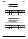
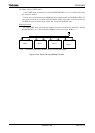
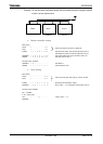
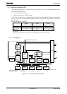
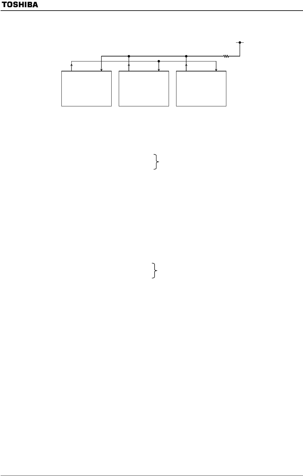
Example: To link two slave controllers serially with the master controller using the system
clock f
IO
as the transfer clock.
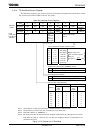
• Master controller setting
Main routine
PFCR ← − − − − − −
01
PFFC ← − − − − − −
X1
Set PF0 to TXD0, and set PF1 to RXD0 pin.
INTES0 ← 1 1 0 0 1 1 0 1 Set INTTX0 to enable, and set interrupt level to level 4.
Set INTRX0 to enable, and set interrupt level to level 5.
SC0MOD0 ← 1 0 1 0 1 1 1 0 Set to 9-bit UART mode, and set transfer clock to f
IO.
SC0BUF ← 0 0 0 0 0 0 0 1 Set select code of slave 1.
Interrupt routine (INTTX0)
SC0MOD0 ← 0 − − − − −
−
−
Set TB8 to “0”.
SC0BUF ← ∗ ∗ ∗ ∗ ∗ ∗ ∗ ∗ Set transmission data.
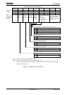
• Slave setting
Main routine
PFCR ← − − − − − −
00
PFFC ← − − − − − −
X1
Set PF0 to TXD (open-drain output), and PC1 to RXD.
INTES0 ← 1 1 0 1 1 110 Set INTTX0 and INTRX0 to enable.
SC0MOD0 ← 0 0 1 1 1 110 Set to <WU> = “1” in 9-bit UART mode transfer clock f
IO.
Interrupt routine (INTRX0)
Acc ← SC0BUF
if Acc = Select code
Then
SC0MOD0
←
− − − 0 − − − − Clear to <WU> = “0”.
TXD RXD
Master
TXD RXD
Slave 1
TXD RXD
Slave 2
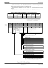
Select code
00000001
Select code
00001010