TMP92CM22
2007-02-16
92CM22-120
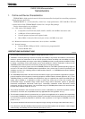
3.8 16-Bit Timer/Event Counters (TMRB)
The TMP92CM22 contains 2 channels 16-bit timer/event counter (TMRB) which have the
following operation modes:
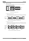
• 16-bit interval timer mode
• 16-bit event counter mode
• 16-bit programmable square wave pulse generation output mode (PPG: Variable duty
cycle with variable period)
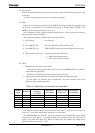
Can be used following operation modes by capture function:
• Frequency measurement mode
• Pulse width measurement mode
• Time differential measurement mode
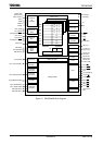
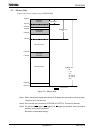
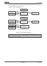
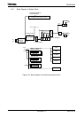
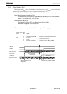
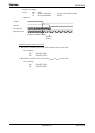
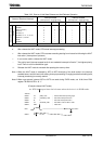
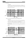
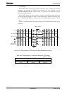
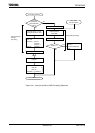
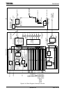
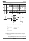
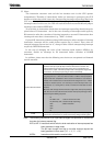
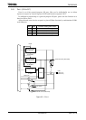
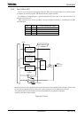
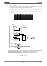
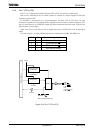
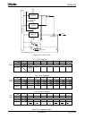
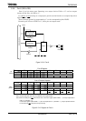
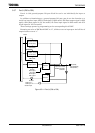
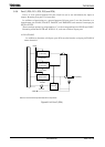
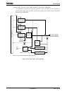
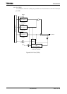
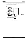
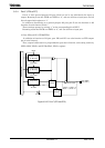
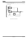
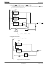
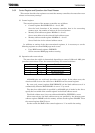
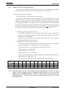
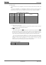
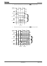
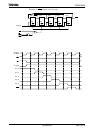
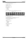
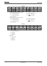
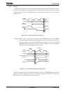
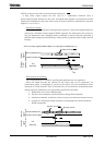
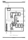
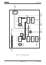
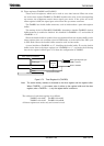
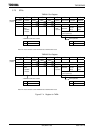
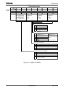
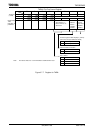
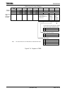
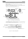
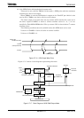
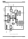
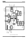
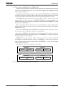
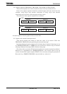
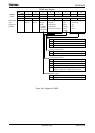
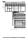
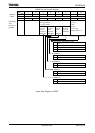
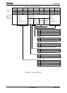
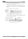
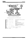
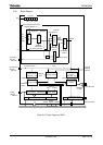
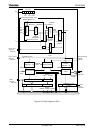
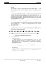
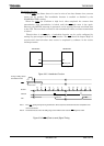
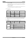
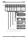
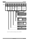
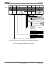
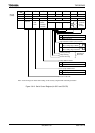
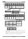
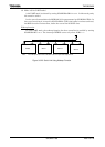
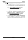
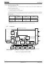
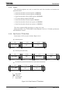
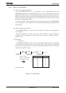
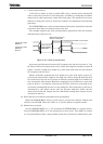
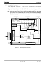
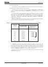
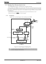
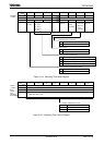
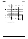
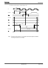
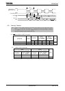
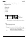
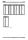
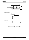
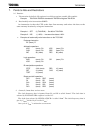
Figure 3.8.1 to Figure 3.8.2 show block diagram of TMRB0 and TMRB1. Each timer/event
counter consists of a 16-bit up counter, two 16-bit timer registers (One of them with a
double-buffer structure), two 16-bit capture registers, two comparators, a capture input
controller, a timer flip-flop and a control circuit.
Each timer/event counter is controlled by 11-byte control register (SFR).
This chapter consists of the following items:
3.8.1 Block diagram
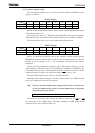
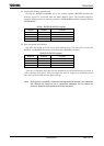
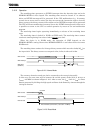
3.8.2 Operation
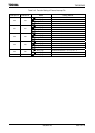
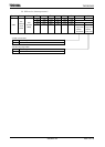
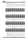
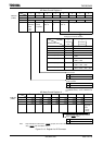
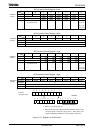
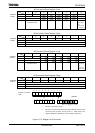
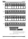
3.8.3 SFRs
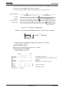
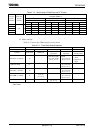
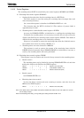
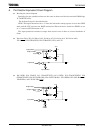
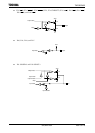
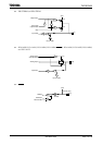
3.8.4 Operation in Each Mode
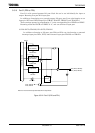
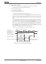
(1) 16-bit interval timer mode
(2) 16-bit event/counter mode
(3) 16-bit programmable pulse generation (PPG) output mode
(4) Capture function examples
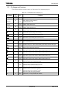
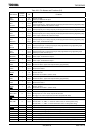
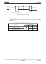
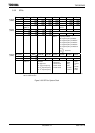
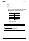
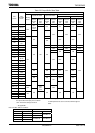
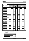
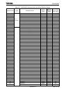
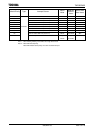
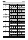
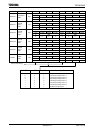
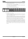
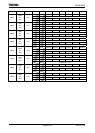
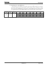
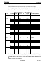
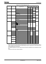
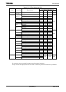
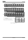
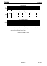
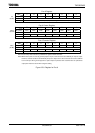
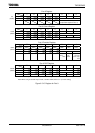
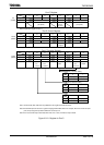
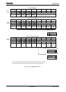
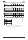
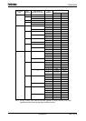
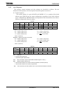
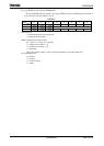
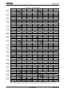
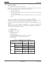
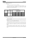
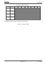
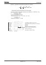
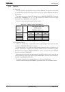
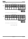
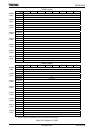
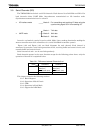
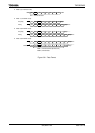
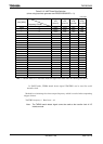
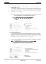
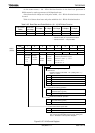
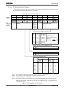
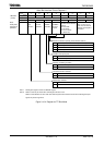
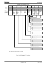
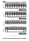
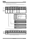
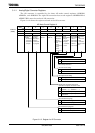
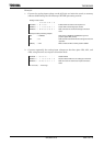
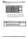
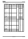
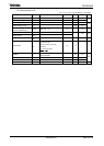
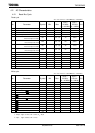
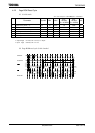
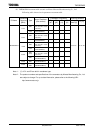
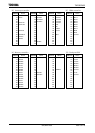
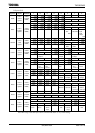
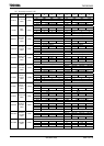
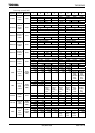
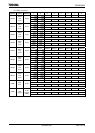
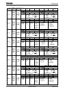
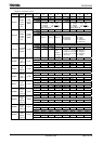
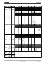
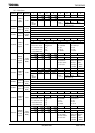
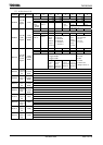
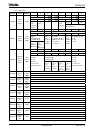
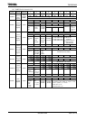
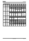
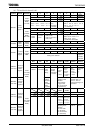
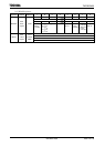
Table 3.8.1 Pins and SFR of TMRB
Channel
Spec
TMRB0 TMRB1
External clock/
Caputre triggr input pin
None
TB1IN0 (Share with PD0)
TB1IN1 (Share with PD1)
External pin
Timer flip-flop output pin
TB0OUT0
(Share with PC6)
TB1OUT0 (Share with PD2)
TB1OUT1 (Share with PD3)
Timre run register TB0RUN (1180H) TB1RUN (1190H)
Timrer mode register TB0MOD (1182H) TB1MOD (1192H)
Timre flip-flop control register TB0FFCR (1183H) TB1FFCR (1193H)
TB0RG0L (1188H) TB1RG0L (1198H)
TB0RG0H (1189H) TB1RG0H (1199H)
TB0RG1L (118AH) TB1RG1L (119AH)
Timer register
TB0RG1H (118BH) TB1RG1H (119BH)
TB0CP0L (118CH) TB1CP0L (119CH)
TB0CP0H (118DH) TB1CP0H (119DH)
TB0CP1L (118EH) TB1CP1L (119EH)
SFR
(Address)
Capture register
TB0CP1H (118FH) TB1CP1H (119FH)