


TMP92CM22
2007-02-16
92CM22-5
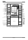
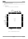
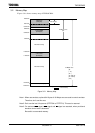
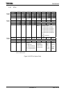
2.2 Pin Names and Functions
The following tables show the names and functions of the input/output pins.
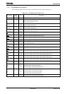
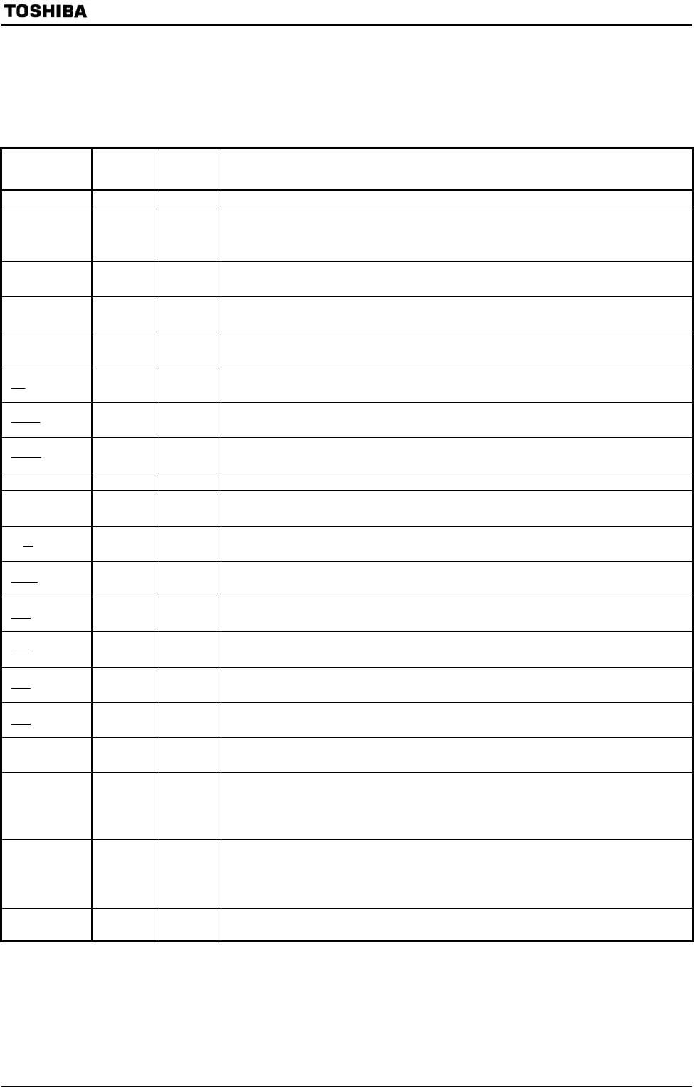
Table 2.2.1 Pin Names and Functions (1/2)
Pin Names
Number
of Pins
I/O Functions
D0 to D7 8 I/O Data (Lower): Data bus D0 to D7.
P10 to P17
D8 to D15
8
I/O
I/O
Port 1: I/O port that allows I/O to be selected at the bit level.
(when used to the external 8-bit bus.)
Data: Data bus D8 to D15.
P40 to P47
A0 to A7
8
I/O
Output
Port 4: I/O port.
Address: Address bus A0 to A7.
P50 to P57
A8 to A15
8
I/O
Output
Port 5: I/O port.
Address: Address bus A8 to A15.
P60 to P67
A16 to A23
8
I/O
Output
Port 6: I/O port.
Address: Address bus A16 to A23.
P70
RD
1
Output
Output
Port 70: Output port.
Read: Strobe signal for reading external memory.
P71
WRLL
1
Output
Output
Port 71: Output port.
Write: Strobe signal for writing data to pins D0 to D7.
P72
WRLU
1
Output
Output
Port 72: Output port.
Write: Strobe signal for writing data to pins D8 to D15.
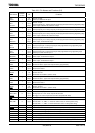
P73 1 Output Port 73: Output port.
P74
CLKOUT
1
Output
Output
Port 74: Output port.
Clock: Output system clock.
P75
R/
W
1
Output
Output
Port 75: Output port.
Read/write: This port is 1 when read and dummy cycle. This port is 0 when write cycle.
P76
WAIT
1
I/O
Input
Port 76: I/O port.
Wait: Pin used to request bus wait to CPU.
P80
CS0
1
Output
Output
Port 80: Output port.
Chip select 0: Outputs 0 when address is within specified address area.
P81
CS1
1
Output
Output
Port 81: Output port.
Chip select 1: Outputs 0 when address is within specified address area.
P82
CS2
1
Output
Output
Port 82: Output port.
Chip select 2: Outputs 0 when address is within specified address area.
P83
CS3
1
Output
Output
Port 83: Output port.
Chip select 3: Outputs 0 when address is within specified address area.
P90
SCK
1
I/O
I/O
Port 90: I/O port.
Serial bus interface clock I/O data at SIO mode.
P91
SO
SDA
1
I/O
Output
I/O
Port 91: I/O port.
Serial bus interface send data at SIO mode.
Serial bus interface send/receive data at I
2
C mode.
(Open-drain output mode by programmable.)
P92
SI
SCL
1
I/O
Input
I/O
Port 92: I/O port.
Serial bus interface receive data at SIO mode.
Serial bus interface clock I/O data at I
2
C mode.
(Open-drain output mode by programmable.)
PA0 to PA2,
PA7
4 Input Port A0 to A2, A7: Input port (with pull-up resistor).